
Component location table
- Make
- Land Rover
- Model
- Discovery Electrical Troubleshooting Manual
- Year
- 1996
- Section
- Circuit diagram › Component location table
COMPONENT LOCATION TABLE
24 COMPONENT LOCATION TABLE
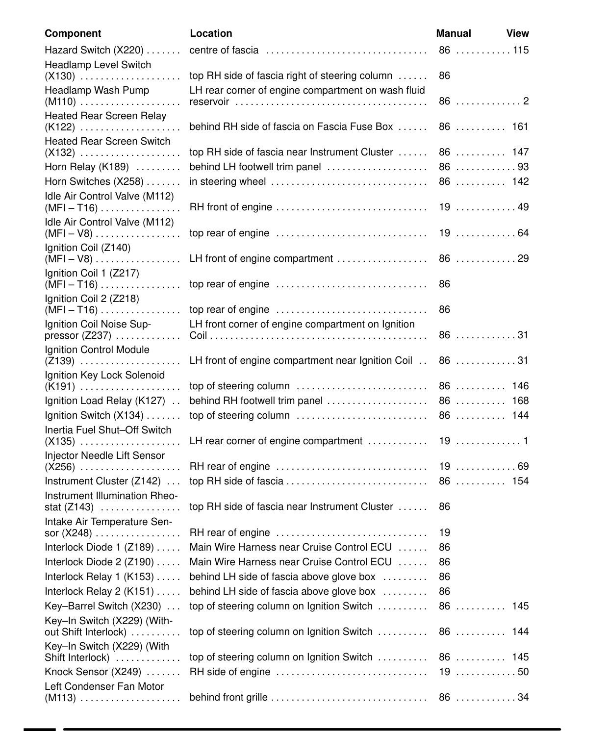
Component Location Hazard Switch (X220) ....... centreoffascia Headlamp Level Switch (X130) .................... top RH side of fascia right of steering column ...... Headlamp Wash Pump LH rear corner of engine compartment on wash fluid 1) RN (<Y=1-107/o 1 <1 Heated Rear Screen Relay (K122) .................... behind RH side of fascia on Fascia Fuse Box ...... Heated Rear Screen Switch (X132) .................... top RH side of fascia near Instrument Cluster ...... Horn Relay (K189) behind LH footwell trimpanel .................... (X258) ....... insteeringwheel ............................... Horn Switches Idle Air Control Valve (M112) (MFI =T16) ................ RHfrontofengine .............................. Idle Air Control Valve (M112) (MFI=V8)................. toprearofengine Ignition Coil (2140) (MFI=V8)................. LHfrontof engine compartment .................. Ignition Coil 1 (2217) (MFI -T16)................ toprearofengine Ignition Coil 2 (Z218) (MFI =T16)................ toprearofengine Ignition Coil Noise SupLH front corner of engine compartment on Ignition (Z237) ............. Coil... iii pressor Ignition Control Module (2139) .................... LHfront of engine compartment Ignition Key Lock Solenoid (K191) .................... topofsteeringcolumn Ignition Load Relay (K127) behind RH footwell trimpanel .................... Ignition Switch (X134)....... topofsteeringcolumn .......................... Inertia Fuel Shut-Off Switch (X135) .................... LHrear corner of engine compartment ............ Injector Needle Lift Sensor (X256) .................... RHrearofengine .............................. Cluster (Z142) ... top RHsideoffascia............................ Instrument Instrument Illumination Rheostat (Z143) top RH side of fascia Intake Air Temperature Sensor(X248)................. RHrearofengine .............................. Diode 1 (2189) ..... Main Wire Harness near Cruise Control ECU Interlock Diode 2 (Z190) ..... Main Wire Harness near Cruise Control ECU Interlock Relay 1 (K153) ..... behind LH side of fascia above Interlock Relay 2 (K151) ..... behind LH side of fascia above Interlock Key—Barrel Switch (X230) top of steering column on Ignition Switch .......... Key—In Switch (X229) (Without Shift Interlock) .......... top of steering column on Ignition Switch .......... Key—In Switch (X229) (With Shift Interlock) ............. top of steering column on Ignition Switch .......... Knock Sensor (X249) ....... RHsideofengine .............................. Left Condenser Fan Motor (M113) .................... behindfrontgrille ...............................
Manual View .......................ccieeee. 86 o.oo... 115
86
J 24 86 .......... 161
86 .......... 147 86 ............98 86 .......... 142
19 ............49
19 ............64
86 ............29
86
86
ee. 86S near Ignition Coil .. 86 ............31
146 86 .......... 86 .......... 168 86 .......... 144
19 .............1
19.069 86 .......... 154
near Instrument Cluster ...... 86
19 86 86 glovebox 86 glovebox 86 86 .......... 145
86 .......... 144
86 .......... 145 19 ............50
86 ............34
Parts & tools for this job For 1996 Land Rover Discovery
- TOOLDigital multimeterSearch: automotive digital multimeter
- PARTAssorted fuse kitSearch: car fuse assortment kit
- TOOLWire crimper and connector kitSearch: wire crimper connector kit
Links open Amazon search results in a new tab. As an Amazon Associate I earn from qualifying purchases.