Discovery II

ENGINE - V8
OVERHAUL 12-2-69
9. Check overall dimensions of gudgeon pin.
Gudgeon pins are only supplied as an
assembly with replacement pistons.
l
Gudgeon pin length = 60.00 to 60.50 mm
(2.362 to 2.382 in).
l
Gudgeon pin diameter = 23.995 to 24.00
mm (0.9446 to 0.9448 in)
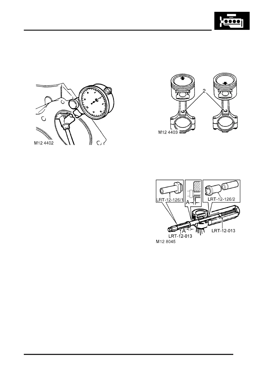
10. Measure cylinder bore wear and ovality in two
axis 40 to 50 mm (1.6 to 2 in) from top of bore.
The temperature of piston and cylinder
block must be the same to ensure accurate
measurement. Do not attempt to de-glaze
cylinder bores.
l
Grade 'A' pistons: Cylinder bore = 94.00 to
94.015 mm (3.7007 to 3.7013 in).
l
Grade 'B' pistons: Cylinder bore = 94.016 to
94.030 mm (3.7014 to 3.7019 in).
l
Maximum ovality = 0.013 mm (0.0005 in).
11. Check alignment of connecting rods.
Reassembly
1. Pistons have a 5 mm (0.2 in) offset gudgeon pin
which can be identified by an arrow mark on
the piston crown. This arrow must always point
towards the front of the engine.
2. Assemble pistons to connecting rods with
arrow on piston pointing towards domed
shaped boss on connecting rod for RH bank of
cylinders and arrow pointing away from domed
shaped boss for LH bank of cylinders.
3. Clamp hexagon body of tool LRT-12-013 in
vice.
4. Screw large nut back until flush with end of
centre screw.
5. Locate remover/replacer adapter LRT-12-126/
2 with its long spigot inside bore of hexagon
body.
6. Fit parallel sleeve, part of tool LRT-12-013,
ensuring that grooved end is towards open end
of tool LRT-12-013. Position sleeve up to
shoulder of centre screw.
7. Lubricate gudgeon pin and bores of connecting
rod and piston with graphite oil.
8. Locate connecting rod and piston to centre
screw with connecting rod entered on parallel
sleeve, part of LRT-12-013 up to the machined
groove on the sleeve.
