
Discovery II
ENGINE - V8
12-2-70 OVERHAUL
9. Fit gudgeon pin on to centre screw and into
piston bore up to connecting rod.
10. Fit remover/replacer bush LRT-12-126/1 with
flanged end towards gudgeon pin.
11. Screw the stop nut on to centre screw and
position piston against groove of tool LRT-12-
126/2.
CAUTION: Ensure that prongs of tool LRT-
12–126/2 remain in contact with piston and
do not contact gudgeon pin.
12. Lock the stop nut securely with the lockscrew.
13. Lubricate centre screw threads and thrust race
with graphite oil, screw large nut up to tool
LRT-12-013.
14. Set torque wrench to 16 Nm (12 lbf.ft) and using
socket on large nut, pull gudgeon pin in until
flange of remover/replacer bushLRT-12-126/1
is 0.40 mm (0.016 in), dimension 'A' from
face of piston. If torque is exceeded during this
procedure, fit of gudgeon pin to connecting rod
is not acceptable and components must be
replaced.
CAUTION: The centre screw and thrust race
must be kept well lubricated throughout the
operation.
15. Dismantle tool, remove piston and check no
damage has occurred during pressing and that
piston moves freely on gudgeon pin.
16. Remove compression rings, oil control rails
and expander from new piston.
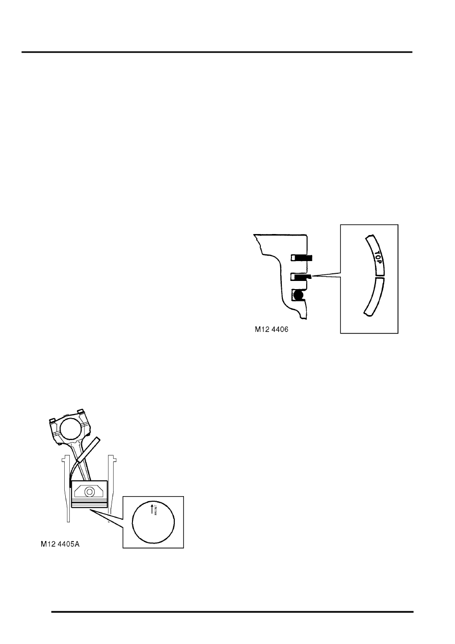
17. Invert piston and with arrow pointing towards
rear of cylinder block, insert piston into cylinder
liner.
18. Position piston with bottom of skirt 30 mm (1.12
in) from top cylinder liner.
19. Using feeler gauges, measure and record
clearance between piston and left hand side of
cylinder- viewed from the front of cylinder
block.
l
Piston to bore clearance = 0.020 to 0.045
mm (0.001 to 0.002 in).
20. Insert piston rings into cylinder bore, use the
piston to hold the rings square to bore and
check the ring gap.
l
1st compression ring = 0.30 to 0.50 mm
(0.012 to 0.02 in).
l
2nd compression ring = 0.40 to 0.65 mm
(0.016 to 0.026 in).
l
Oil control ring rails = 0.38 to 1.40 mm
(0.015 to 0.055 in).
21. Remove piston rings from bore.
22. Fit oil control ring rails and expander, ensuring
ends butt and do not overlap.
23. Fit 2nd compression ring marked 'TOP' with
marking uppermost in 2nd groove.
24. Fit 1st compression ring in first groove either
way round.
25. Check piston ring to groove clearance.
l
1st compression ring = 0.05 to 0.10 mm
(0.002 to 0.004 in).
l
2nd compression ring = 0.05 to 0.10 mm
(0.002 to 0.004 in).
26. Position oil control expander ring joint and ring
rail gaps all at one side, between gudgeon pin
and away from LH side of piston - viewed from
front of piston. Position the gaps in ring rails
approximately 25 mm (1.0 in) each side of
expander ring joint.
27. Position compression rings with gaps on
opposite side of piston between gudgeon pin
and RH side of piston - viewed from front of
piston.
28. Thoroughly clean cylinder bores.
29. Lubricate piston rings and gudgeon pin with
clean engine oil.
30. Lubricate cylinder bore with clean engine oil.