
300Tdi Discovery
70
BRAKES
8
DESCRIPTION AND OPERATION
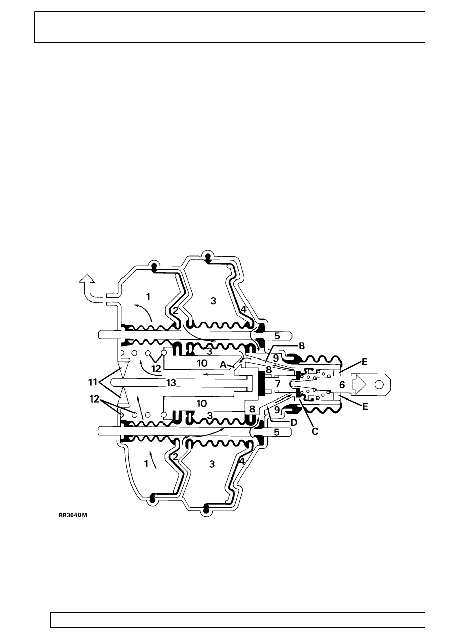
Brakes applied
When the brake pedal is depressed the pedal pushrod
operates valve C situated in the plastic diaphragm hub
9 and 10. Inital depression of the the brake pedal,
push rod 6 and plunger 7 compress a rubber pad 8.
This slight movement causes valve C to close port D
sealing off the vacuum to chambers 2/4 and allows
atmospheric pressure to enter the chambers through
the air filter E.
With depression in chambers 1/3 and air pressure in
chambers 2/4 the servo hub will apply the brakes via
the master cylinder push rod 13.
Atmospheric pressure over the large area of the
diaphragms multiples the force applied to the master
cylinder piston, to provide the power assistance. If the
brake pedal is only partially depressed, the servo hub,
diaphragms and master cylinder push rod will stop
moving, when valve C comes to rest on the plunger 7.
At this point the valve will balance the pressure in all
the chambers, to the applied effort at the pedal and
provide proportional braking.
It is only when the brakes are fully applied that the
valve does not balance the pressures in all the
chambers, but ensures that maximum available
depression is in chambers 1/3 and full atmospheric
pressure enters chambers 2/4.
When the brake pedal is released, the pressure in all
chambers is equalised and the servo is returned to the
rest position by spring 12.