
300Tdi Discovery
70
BRAKES
22
REPAIR
MODULATOR UNIT
Service repair no - 70.65.45
WARNING: New modulator units are
supplied in a shock absorbing pack
marked with a use by date. The new
modulator will contain hydraulic brake fluid within
the valve block and all ports plugged.
Modulator units must be handled with care the
following must be avoided:- any impact, use of
compressed air on any of the hydraulic ports,
removing plugs to connection ports before fitting
unit.
Remove
1. Refer to the illustration of brake components
ABS. For details of modulator unit and hydraulic
pipe connections to it.
See Brake
Components ABS
2. Refer to general brake service practice.
See
General Brake Service Practice
3. Check new modulator unit is packaged in
accordance with the WARNING above.
4. Disconnect battery negative lead.
5. Remove the two electrical plugs.
6. Identify 8 pipe to modulator connections for
correct reassembly.
7. Disconnect 8 pipe unions.
8. Remove nuts securing modulator to mounting
bracket.
9. Remove modulator unit.
10. Remove mounting bushes and cup.
Refit
11. Fit mounting bushes and cup to new modulator.
12. Fit modulator unit to mounting bracket.
13. Fit 8 pipes to modulator connections. Pipes
must be connected to correct port. Tighten to
15Nm.
14. Bleed the complete hydraulic system.
See
Brake System Bleed
15. Check system function using the ’Testbook’
diagnostics
16. Test operation of brakes.
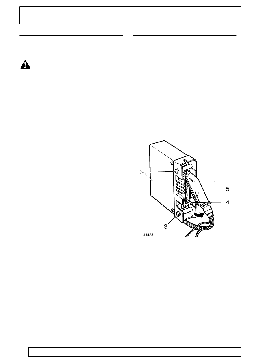
ELECTRONIC CONTROL UNIT ABS
Service repair no - 70.65.01
Remove
For location of the ECU.
See Description and
operation, ABS Components
1. Disconnect battery negative lead.
2. Remove retaining bolt and lower alarm system
ECU and relay mounting bracket into passenger
footwell.
3. Remove two screws and detach ECU complete
with harness plug from mounting bracket.
4. Release ECU plug retaining clip.
5. Move plug in direction of arrow and release
hooked end of plug from retaining post.
Refit
6. Reconnect ECU harness plug ensuring that it is
firmly located and retaining clip secures plug.
7. Reverse removal procedure.