
300Tdi Discovery
SUPPLEMENTARY RESTRAINT SYSTEM
7
REPAIR
ROTARY COUPLER CENTRALISE
Fitting a rotary coupler which has not been centralised
could result in tape breakage. If the tape is broken, a
new rotary coupler must be fitted.
Providing the removal procedure has been correctly
followed this operation should not be necessary. If
however there is evidence of tampering, it is
imperative that the coupler is centralised.
CAUTION: Ensure wheels are positioned
straight ahead before fitting the rotary
coupler.
1. Correctly fit rotary coupler to column switch
assembly but do not fit steering wheel or make
any electrical connections.
See rotary coupler.
2. Depress rotary coupler locking peg and without
using undue force, rotate coupler anti-clockwise
as far as inner tape will allow. Releasing peg will
lock coupler in its current position.
NOTE: Do not apply excessive force when
limit is reached as this may result in tape
breakage. If no limit can be found, tape
has already broken and rotary coupler must be
replaced.
3. Having turned rotary coupler fully anti-clockwise
to limit position, proceed to turn coupler 2.5 turns
clockwise to obtain central position. (Coupler will
normally rotate a full five turns from
anti-clockwise limit to clockwise limit).
4. Make necessary electrical connections and refit
steering wheel.
See steering wheel.
5. Refit driver’s airbag module.
See driver’s
airbag module.
COLUMN SWITCH ASSEMBLY
Service repair no - Indicator/lighting - 86.65.55
Service repair no - Wash/wipe - 84.15.34
Remove
1. Remove steering wheel.
See steering wheel.
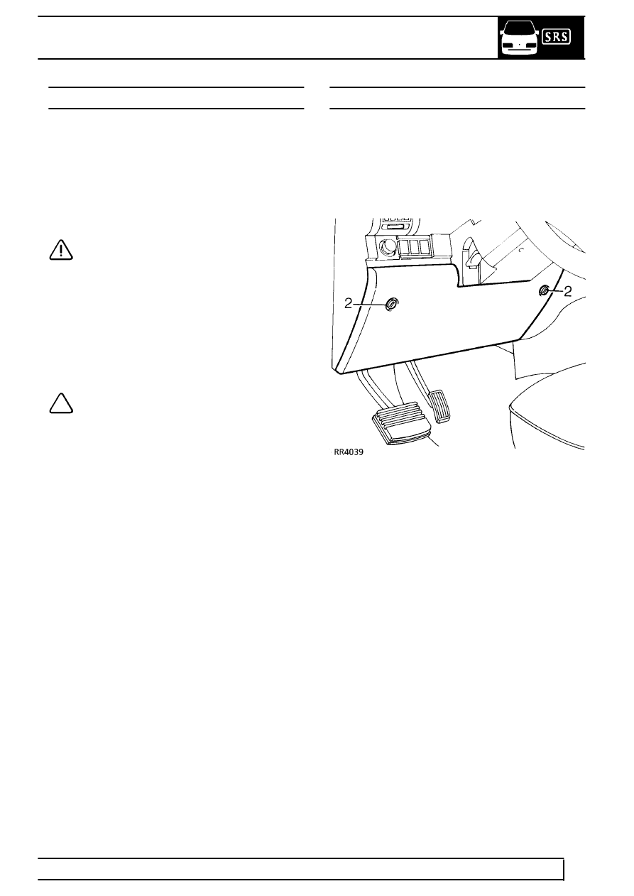
2. Release 2 turnbuckles and remove lower dash
panel.