
300Tdi Discovery
76
CHASSIS AND BODY
14
REPAIR
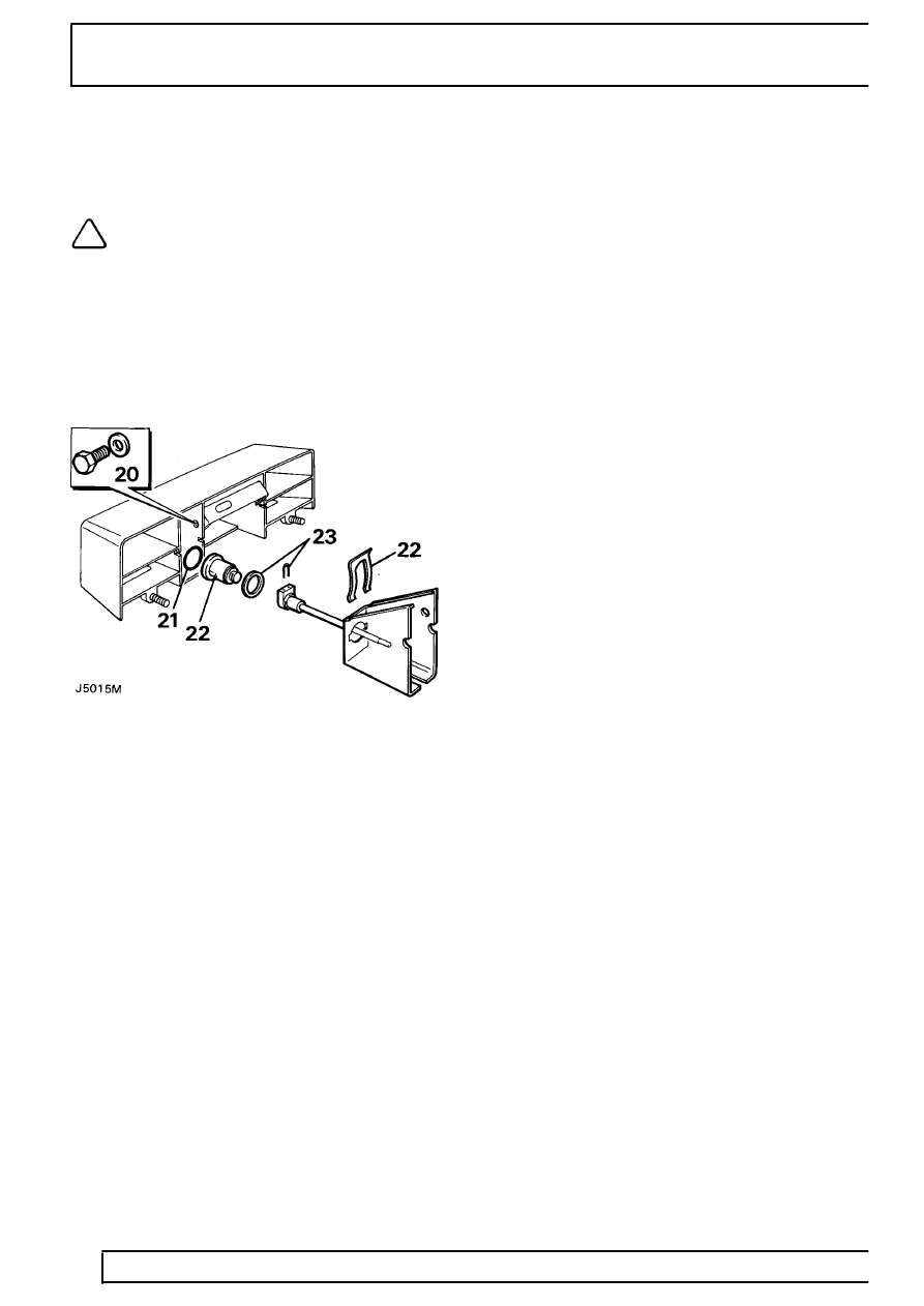
Lock barrel and number plate light housing
Disassemble
NOTE: The lock barrel can only be
removed from its housing when the lock
barrel and number plate light housing is
removed from the door.
20. Remove the bolt securing the lock barrel
mounting bracket to the housing and withdraw
the assembled barrel and bracket.
21. Remove the ’O’ ring seal from inside the
housing.
22. Remove the spring clip securing the barrel to the
bracket and withdraw the barrel and stem
assembly from the bracket complete with seal.
23. Remove the ’U’ clip securing the stem to the
barrel and detach the seal from the inner face of
the barrel.
24. If the lock barrel and number plate light housing
is being renewed, remove the number plate
lights, harness and the housing mounting
bracket, from the existing housing and fit them to
the new housing.
Reassemble
25. Fit the stem to the barrel and secure with the ’U’
clip.
26. Position a new seal on the inner face of the
barrel, insert the stem and barrel into the
mounting bracket and secure with the spring clip.
27. Place a new ’O’ ring seal on the inner face of the
barrel aperture in the housing.
28. Insert the assembled bracket and barrel into its
location in the housing, taking care not to disturb
the seal, and secure with the bolt.
Refit
29. Fit the outer handle to the door and secure from
the inside with the two nuts and washers.
30. Fit the lock barrel and number plate light housing
by inserting the number plate light leads through
the aperture in the door panel and locating the
rubber grommet in the aperture. Insert the barrel
stem through the door, locate the housing on the
door panel, ensure that the seal seats correctly,
and secure with the single bolt and washer
through the logo aperture.
31. Connect the number plate light leads to the door
harness.
32. Fit the logo to the aperture in the housing.
33. Fit the fulcrum and connecting rod to the barrel
stem and secure with secure with the ’E’ clip.
34. Fit the lock and assembled outer ’Y’ lever,
secure the lock with the three screws, locate the
’Y’ lever pivot and secure with the pin.
35. Fit the connecting rod from the outer handle
lever to the outer ’Y’ lever.
36. Fit the childproof lock actuator and check that it
is functioning.
37. Insert the remote button and rod to the location
in the door.
38. Offer up the assembled inner ’Y’ lever and
bracket, attach the barrel connecting rod to the
top clip of the upper leg and the rod from the
lock to the lower clip of the upper leg.
39. Locate the barrel stem in the insert on the
bracket.
40. Secure the bracket with the four screws; fitting
the door pull mounting bracket under the heads
of the top two screws.
41. Attach the remote button and the actuator
connecting rods to the ’Y’ lever.
42. Fit the inner release handle and attach the
connecting rod to the lock.
43. Refit the vapour protective sheet, door trim panel
and door pull.