
Hose clips
- Make
- Land Rover
- Model
- Freelander Workshop Manual
- Year
- 1998–2000
- Section
- General precautions and fitting instructions › Hose clips
Hose clips
- Markings are usually provided on the hose to indicate the the correct clip position. If no markings are provided, position the clip directly behind the retaining lip at the end of the stub as shown.
- Worm drive clips should be oriented with the crimped side of the drive housing facing towards the end of the hose, or the hose may become pinched between the clip and the stub pipe retaining lip.
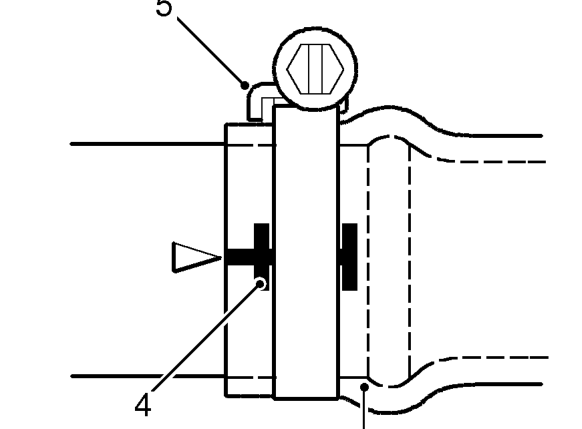
- Worm drive clips should be tightened to 3Nm (2 lbf.ft) unless otherwise stated.
CAUTION: Ensure that hose clips do not foul adjacent components.
Heat protection
- Always ensure that heatshields and protective sheathing are in good condition. Replace if damage is evident.
- Particular care must be taken when routing hoses close to hot engine components, such as the exhaust manifold and the Exhaust Gas Recirculation (EGR) pipe.
CAUTION: Hoses will relax and deflect slightly when hot; ensure this movement is taken into account when routing and securing hoses.
SERVICE TOOLS AND GARAGE EQUIPMENT
Special service tools have been developed to facilitate removal, dismantling and assembly of mechanical components in a cost effective and time efficient manner. The use of such special tools also helps prevent the potential for damage to components. Some operations described in this Manual cannot be carried out properly without the aid of the relevant service tools.
Where specific garage equipment is required for diagnosis and repair, reference should be made to the Service Tools and Equipment Programme where details of the equipment recommended by Land Rover Service may be found.
Parts & tools for this job For 1998 Land Rover Freelander
- TOOLTorque wrenchSearch: 3/8 inch torque wrench
- TOOLSocket setSearch: socket set metric
- BOOKHaynes manualSearch: Haynes manual Land Rover Freelander
Links open Amazon search results in a new tab. As an Amazon Associate I earn from qualifying purchases.