
Heating & ventilation (Blower): Description and operation
- Make
- Land Rover
- Model
- Freelander Workshop Manual
- Year
- 1998–2000
- Section
- Description and operation › Blower
Blower
The blower controls the volume of air being supplied to the distribution outlets. The blower is installed in the driver’s side of the casing and consists of an open hub, centrifugal fan powered by an electric motor. The open end of the fan surrounds the air inlet, which is on the passenger’s side of the casing. The blower switch and the resistor pack control the operation of the blower, which can be selected to run at one of four speeds.
Resistor pack
The resistor pack supplies reduced voltages to the blower motor for blower speeds 1, 2 and 3. For blower speed 4, the resistor pack is bypassed and
battery voltage drives the motor at full speed. The pack is installed in the RH side of the casing, in the air outlet from the blower fan, so that any heat generated is dissipated by the air flow.
Interior view of heater assembly (RH drive shown, LH drive similar)
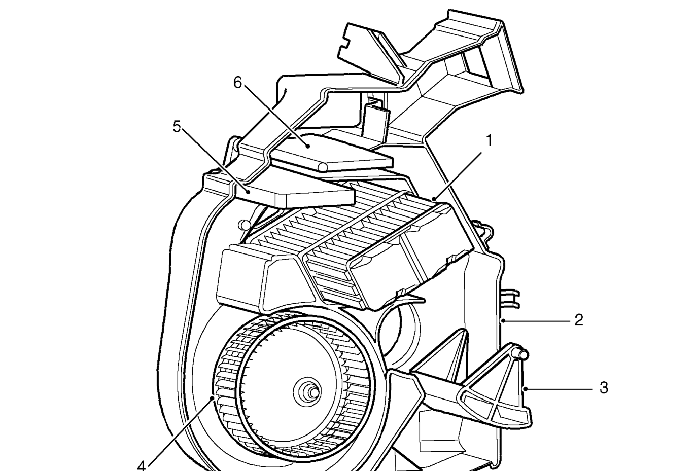
- Heater matrix
- Casing
- Distribution main flap
- Blower fan
- Blend flap
- Distribution fresh air flap
Parts & tools for this job For 1998 Land Rover Freelander
- TOOLA/C manifold gauge setSearch: AC manifold gauge set
- TOOLUV leak detection kitSearch: AC UV leak detection kit
- PARTCabin filterSearch: Land Rover Freelander 1998 cabin filter
Links open Amazon search results in a new tab. As an Amazon Associate I earn from qualifying purchases.