Freelander System Description and Operation

AIR CONDITIONING
DESCRIPTION AND OPERATION
82-13
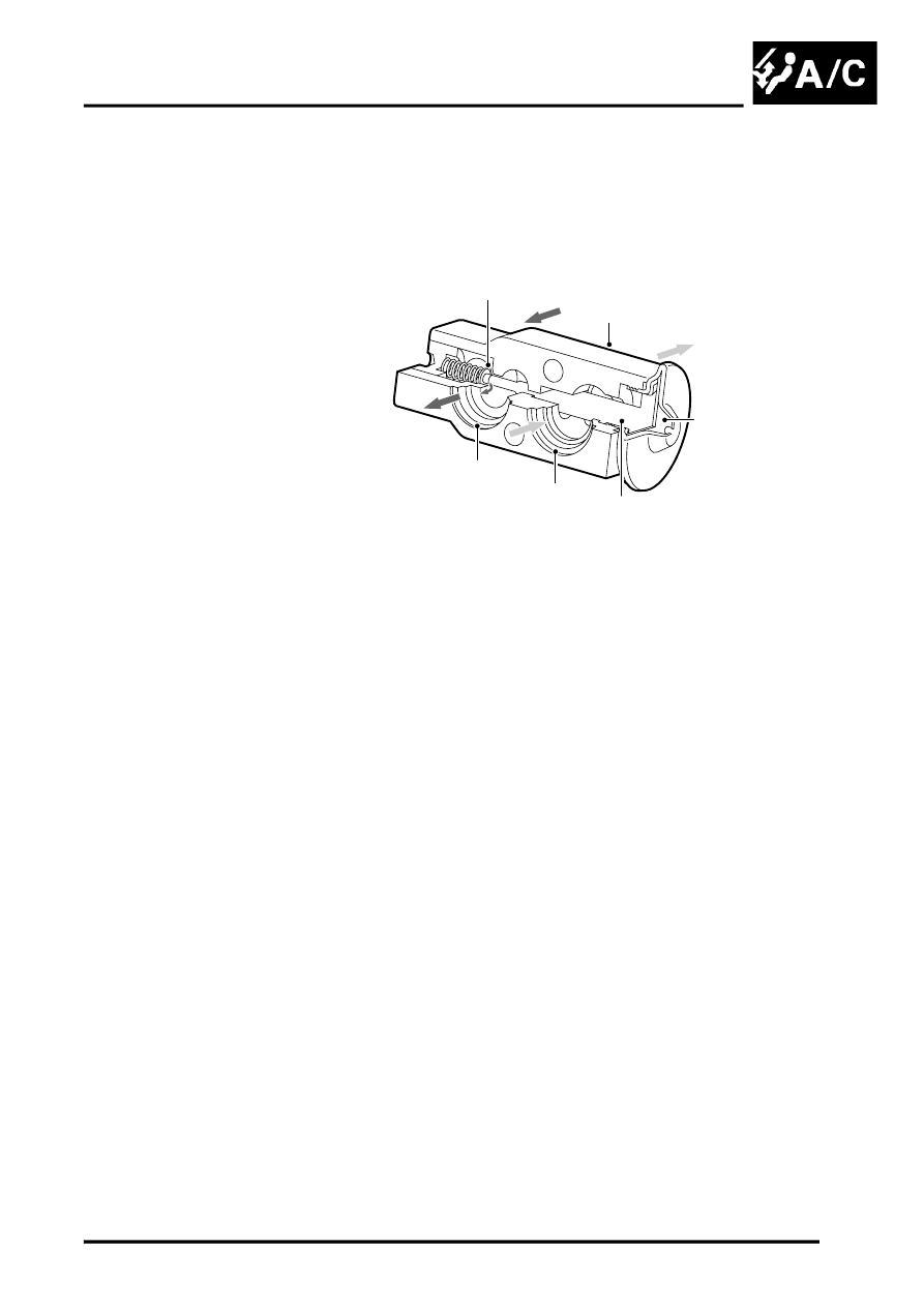
The thermostatic expansion valve is attached to the inlet and outlet ports of the evaporator, in the cooling unit behind
the passenger's side of the fascia. The valve is the parallel charge type, consisting of an aluminium housing containing
inlet and outlet passages. A ball and spring metering valve is installed in the inlet passage and a temperature sensor
is installed in the outlet passage. The temperature sensor consists of a push rod connected to a diaphragm. The
bottom end of the push rod acts on the ball of the metering valve. Pressure on top of the diaphragm is controlled by
evaporator outlet temperature conducted through the push rod. The bottom of the diaphragm senses evaporator outlet
pressure via internal passages.
1 Diaphragm
2 Housing
3 Metering valve
4 Inlet passage to evaporator
5 Outlet passage from evaporator
6 Temperature sensitive tube
Liquid refrigerant flows through the metering valve into the evaporator. The restriction across the metering valve
reduces the pressure and temperature of the refrigerant. The restriction also changes the solid stream of refrigerant
into a fine spray, to improve the evaporation process. As the refrigerant passes through the evaporator, it absorbs
heat from the air flowing through the evaporator matrix. The increase in temperature causes the refrigerant to
vapourise and increase in pressure.
The temperature and pressure of the refrigerant leaving the evaporator act on the diaphragm and temperature
sensitive tube, which move to regulate the metering valve opening and so control the volume of refrigerant flowing
through the evaporator. The warmer the air flowing through the evaporator matrix, the more heat available to
evaporate refrigerant and thus the greater the volume of refrigerant allowed through the metering valve.
M82 0720
6
5
1
3
2
4
