Freelander Service Procedures

GENERAL INFORMATION
03-15
Fuel System Hoses
All fuel hoses are made up of two laminations, an
armoured rubber outer sleeve and an inner viton
core. If any of the fuel system hoses have been
disconnected, it is imperative that the internal bore is
inspected to ensure that the viton lining has not
become separated from the armoured outer sleeve.
A new hose must be fitted if separation is evident.
Cooling system hoses
The following precautions MUST be followed to
ensure that integrity of cooling hoses and their
connections to system components are maintained.
Hose orientation and connection
Correct orientation of cooling hoses is important in
ensuring that the hose does not become fatigued or
damaged through contact with adjacent
components.
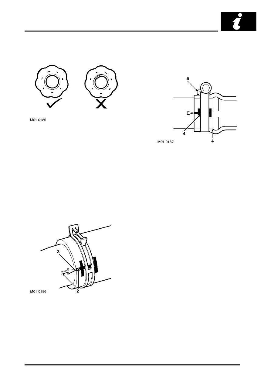
Where 'timing' marks (2) are provided on the hose
and corresponding connection, these must be used
to ensure correct orientation.
Hoses must be pushed fully onto their connection
points. Usually, a moulded form (3) on the stub pipe
provides a positive indicator.
Hose clips
Markings (4) are usually provided on the hose to
indicate the correct clip position. If no markings are
provided, position the clip directly behind the
retaining lip at the end of the stub as shown.
Worm drive clips should be oriented with the crimped
side of the drive housing (5) facing towards the end
of the hose, or the hose may become pinched
between the clip and the stub pipe retaining lip.
Worm drive clips should be tightened to 3 Nm (2
lbf.ft) unless otherwise stated.
Ensure that hose clips do not foul adjacent
components.
