
L322 Range Rover Service Procedures
RESTRAINT SYSTEMS
75-10
REPAIRS
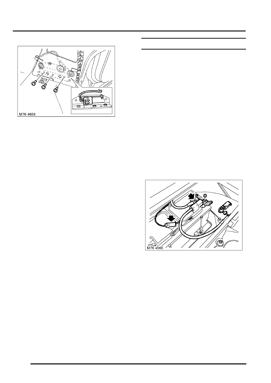
6. Remove and discard 3 Torx bolts securing side
impact crash sensor retaining bracket to 'B'
post.
7. Release harness from retaining clips and
disconnect multiplug from side impact crash
sensor.
8. Remove side impact crash sensor and
retaining bracket from 'B' post.
Refit
NOTE: If the SRS component is to be replaced,
the bar code of the new unit must be recorded.
1. Position side impact crash sensor and retaining
bracket to 'B' post, secure harness and connect
multiplug to side impact crash sensor.
2. Fit new bolts to side impact crash sensor
retaining bracket and tighten to 8 Nm (6 lbf.ft).
3. Position seat belt reel to 'B' post, fit Torx bolt
and tighten to 31 Nm (23 lbf.ft).
4. Fit centre carpet retainer to 'B' post and secure
with scrivets.
5. Fit front and rear carpet retainers.
6. Fit 'B' post finisher.
Trim finisher - 'B' post - upper.
7. Connect the battery earth lead.
8. New sensors require programming:
l
Turn ignition to position 'II'
l
SRS warning light will flash for a period of
approximately 30 seconds
l
Turn ignition off
l
Sensor programming is now complete
Battery - disconnect unit (SRS)
$% 76.74.14
Before disconnecting the battery, ensure all text and
cautions in the battery disconnection section are
observed.
GENERAL INFORMATION, Electrical
WARNING: It is imperative that before any work
is undertaken on the SRS system, the
appropriate information is read thoroughly.
WARNING: Always disconnect both battery leads
before beginning work on the SRS system.
Disconnect the negative lead first. Never reverse
connect the battery.
Remove
1. Make the SRS system safe.
Supplementary Restraint System (SRS)
Precautions.
2. Release cover and remove nut securing
positive lead to the battery disconnect unit.
Position the positive lead aside.
3. Release cover and loosen nut securing battery
disconnect unit to the battery terminal.
4. Disconnect multiplug from the battery
disconnect unit.
5. Remove cover and nut securing battery
disconnect unit to the junction box.
6. Remove the battery disconnect unit.