
LR3/Disco 3
Each side air curtain has an inflator, which is attached to the D pillar by a mounting bracket and two screws. The inflator is
connected to the air curtain by a gas guide pipe. The gas guide pipe and air curtain are secured to the cant rail by two
screws. Tethers are attached to the front and rear of the air curtain. The front tether is anchored to the C pillar. The rear
tether is anchored to the D pillar and held in position by a tether housing.
When a third row side air curtain deploys, it extends downwards from behind the headliner. The expanding air curtain
tightens the tethers, which retain the air curtain in position against the rear quarter window.
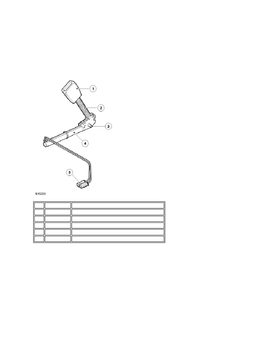
PRETENSIONERS
The pretensioners are used to tighten the front safety belts during a collision to ensure the occupants are securely held in
their seats. A pretensioner is integrated into each front safety belt buckle.
Each pretensioner has a tube containing an inflator and a piston. The inflator is connected to the RCM (restraints control
module) . The piston is attached to a steel cable, the opposite end of which is attached to the safety belt buckle.
On receipt of a fire signal from the RCM (restraints control module) , the inflator generates nitrogen gas that rapidly
expands to drive the piston along the tube, pulling the cable and drawing the safety belt buckle downwards.
SAFETY BELT SENSORS
The buckle of each front safety belt incorporates a Hall effect sensor that provides a safety belt status signal to the RCM
(restraints control module) . The RCM (restraints control module) broadcasts the status of the two front safety belts on the
high speed CAN (controller area network) bus for use by the instrument cluster.
IMPACT SENSORS
Item Part Number
Description
1
-
Safety belt buckle
2
-
Boot
3
-
Anchor bolt
4
-
Piston and tube
5
-
Electrical connectors for inflator and buckle switch