Range Rover Classic

MFI
13
REPAIR
44. Grease new air seal with Admax L3 or
Energrease LS3. Push seal down shaft, into
counterbore until seal is 6.0 mm (0.236 in) below
face of plenum.
Throttle levers and bracket - assemble
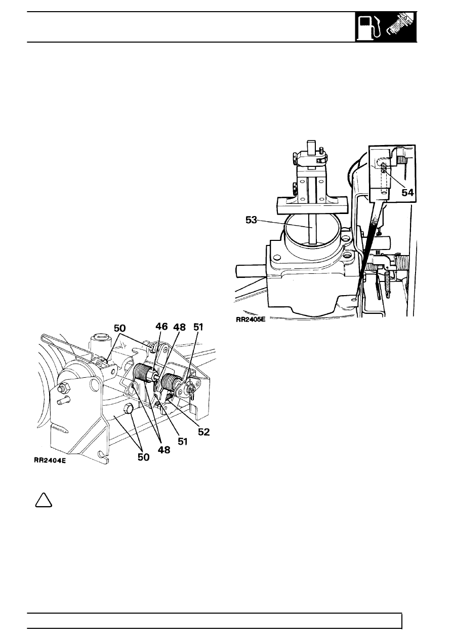
45. Fit stop lever to throttle shaft, a new tab washer
and secure with throttle shaft nut.
46. Holding stop lever on stop, tighten throttle shaft
nut securely, bend over tabs to lock nut in
position.
47. Fit inboard throttle return spring noting that small
hooked end of spring is nearest plenum.
48. Locate hooked end of inboard spring on stop
lever. Wind up straight end one full turn and
locate in appropriate slot.
49. Fit countershaft to interconnecting nut of throttle
valve shaft.
50. Secure throttle bracket assembly to plenum.
Secure with three retaining bolts.
51. Ensure hooked end of outboard spring is
retained by lever, wind spring up one full turn
and locate free end in appropriate slot.
52. Fit overtravel spring.
Lightly grease throttle return and overtravel
springs with Admax L3 or Energrease LS3.
NOTE: If new throttle levers have been
fitted, minimum throttle setting of disc
must be checked to ensure it is 90˚ to
bore.
53. Using a depth vernier or depth micrometer,
check dimension from mouth of bore to top and
bottom of valve disc. Dimension must be within
0.5 mm (0.019 in) total indicator reading across
diameter of disc.
54. If dimension is out of limits, adjust small set
screw below stop lever.
Refit
55. Reconnect and adjust cruise control actuator
link.
See Actuator Link Setting
56. Clean joint faces of plenum and ram housing.
Apply ’Hylomar’ sealant, refit plenum chamber.
Tighten bolts to
26 Nm.
57. Reverse removal procedure.
