
PLENUM CHAMBER
- Make
- Land Rover
- Model
- Range Rover Classic
- Section
- REPAIR › PLENUM CHAMBER
19
FUEL SYSTEM
8
REPAIR
10. Remove fuel rail and injectors.
11. Remove injector retaining clips, ease injectors
from rail. Remove and discard ’O’ rings from
injectors.
12. Remove fuel pressure regulator if required.
Refit
13. Fit NEW ’O’ rings, to injectors. Lightly coat ’O’
rings with silicon grease 300. Insert injectors into
fuel rail, multi-plug connections facing outwards.
14. Refit retaining clips.
CAUTION: Care must be taken when
refitting the fuel rail and injectors to intake
manifold to prevent damage to ’O’ rings.
15. Fit a NEW ’O’ ring to pressure regulator lightly
coat ’O’ ring with silicon grease 300 and secure
regulator to the fuel rail.
16. Fit fuel rail and heater pipe assemblies to intake
manifold. Secure rail and pipes in position with
five bolts.
17. Reverse removal procedure. 2 to 7.
18. Pressurise fuel system and check for fuel leaks
around injectors and pressure regulator.
PLENUM CHAMBER
Service repair no - 19.22.46
Includes throttle levers and throttle disc
Remove
1. Disconnect battery negative lead.
2. Disconnect electrical multi-plug from bypass air
valve.
3. Disconnect vacuum hose adjacent to bypass air
valve.
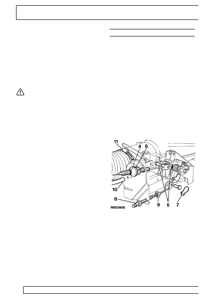
4. Mark an identification line on throttle cable outer
to assist re-assembly.
5. Remove clevis pin from throttle cable.
6. Pry adjustment thumb wheel from throttle
bracket. Lay cable aside.
7. Remove retaining clip and clevis pin from kick
down cable (automatic vehicles).
8. Apply adhesive tape behind rear adjustment nut
on kick down cable to prevent nut moving.
9. Remove front lock nut. Remove cable and lay
aside.
10. Remove cruise control vacuum hose.
11. Remove intake hose from neck of plenum
chamber.
12. Disconnect throttle position sensor multi-plug.
13. Remove PCV breather hose.
14. Disconnect two coolant hoses and plug each
hose to prevent excessive loss of coolant.
Identify each hose for re-assembly.
Parts & tools for this job For Land Rover Range Rover
- PARTFuel filterSearch: Land Rover Range Rover fuel filter
- TOOLFuel pressure test kitSearch: fuel pressure test kit
- TOOLFuel line disconnect toolSearch: fuel line disconnect tool
Links open Amazon search results in a new tab. As an Amazon Associate I earn from qualifying purchases.