
70 - BRAKES - ELECTRONIC TRACTION CONTROL (page 6 of 16)
- Make
- Land Rover
- Model
- Range Rover Classic
70
BRAKES
4
REPAIR
HYDRAULIC BOOSTER UNIT
Service repair no - 70.65.20
Remove
CAUTION: Do not allow booster unit to be
dropped or rested on its front face.
Damage to plastic tangs of multiplug could
occur, requiring fitting a new booster unit
1. Disconnect battery negative lead. Depressurise
system.
See Depressurising System
2. Thoroughly clean area around booster unit outlet
ports and electrical connector.
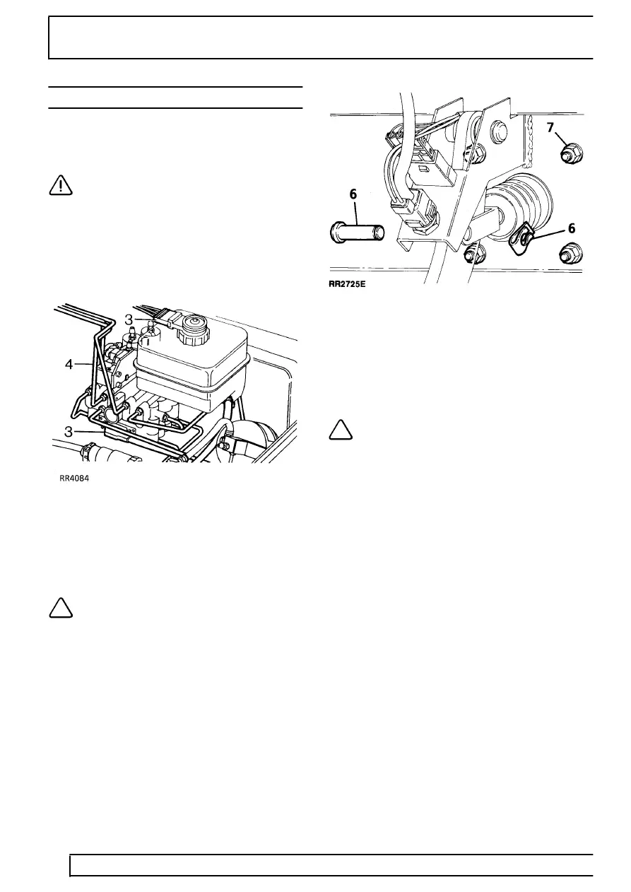
3. Disconnect electrical multiplug and connector
from low fluid switch. Remove booster earth
strap.
4. Remove brake pipes and hydraulic pipes to
accumulator and hydraulic power unit.
NOTE: Each outlet port is numbered, each
brake pipe is marked with corresponding
number for reassembly. Immediately seal
each pipe and outlet port to prevent ingress of
foreign matter.
5. Inside vehicle: Remove lower dash panel and
knee bolster, where fitted.
6. Release spring clip and clevis pin from brake
pedal.
7. Remove 4 nuts securing booster unit.
8. Remove booster unit.
Refit
NOTE: New booster units are supplied in a
sealed pack marked with a ’use by’ date.
DO NOT fit a booster if date has elapsed,
or if pack is not sealed. DO NOT open sealed pack
until ready to fit unit.
9. Reverse removal procedure. Ensuring correct
fitting of pipes. Tighten booster fixings to
25 Nm
and pipes to
15 Nm.
10. Fit clevis pin into UPPER of two holes in brake
pedal.
11. Adjust brake light switch: pull red (later vehicles,
white) sleeve and black plunger fully forward.
Pull brake pedal back fully to reset switch.
12. Bleed brake system.
See Brake System Bleed
(ABS)
Parts & tools for this job For Land Rover Range Rover
- PARTBrake padsSearch: Land Rover Range Rover brake pads
- TOOLBrake bleeder kitSearch: one man brake bleeder kit
- FLUIDBrake fluidSearch: brake fluid
Links open Amazon search results in a new tab. As an Amazon Associate I earn from qualifying purchases.