
6 L4-2.5L (2010)
*1
Calculated value; differs from terminal voltage
*2
MTX
*3
Vehicles equipped with cruise control switch
-
Following PIDs are for the ATX models. If inspects for following PIDs, See: Powertrain Management/Transmission Control Systems/Testing and
Inspection/Scan Tool Testing and Procedures/On-Board Diagnostic System PID/Data Monitor Inspection - FS5A-EL
Without Using the SST
CAUTION:
-
The PCM terminal voltages vary with change in measuring conditions and vehicle conditions. Always carry out a total inspection of the input
systems, output systems, and PCM to determine the cause of trouble. Otherwise, a wrong diagnosis will be made.
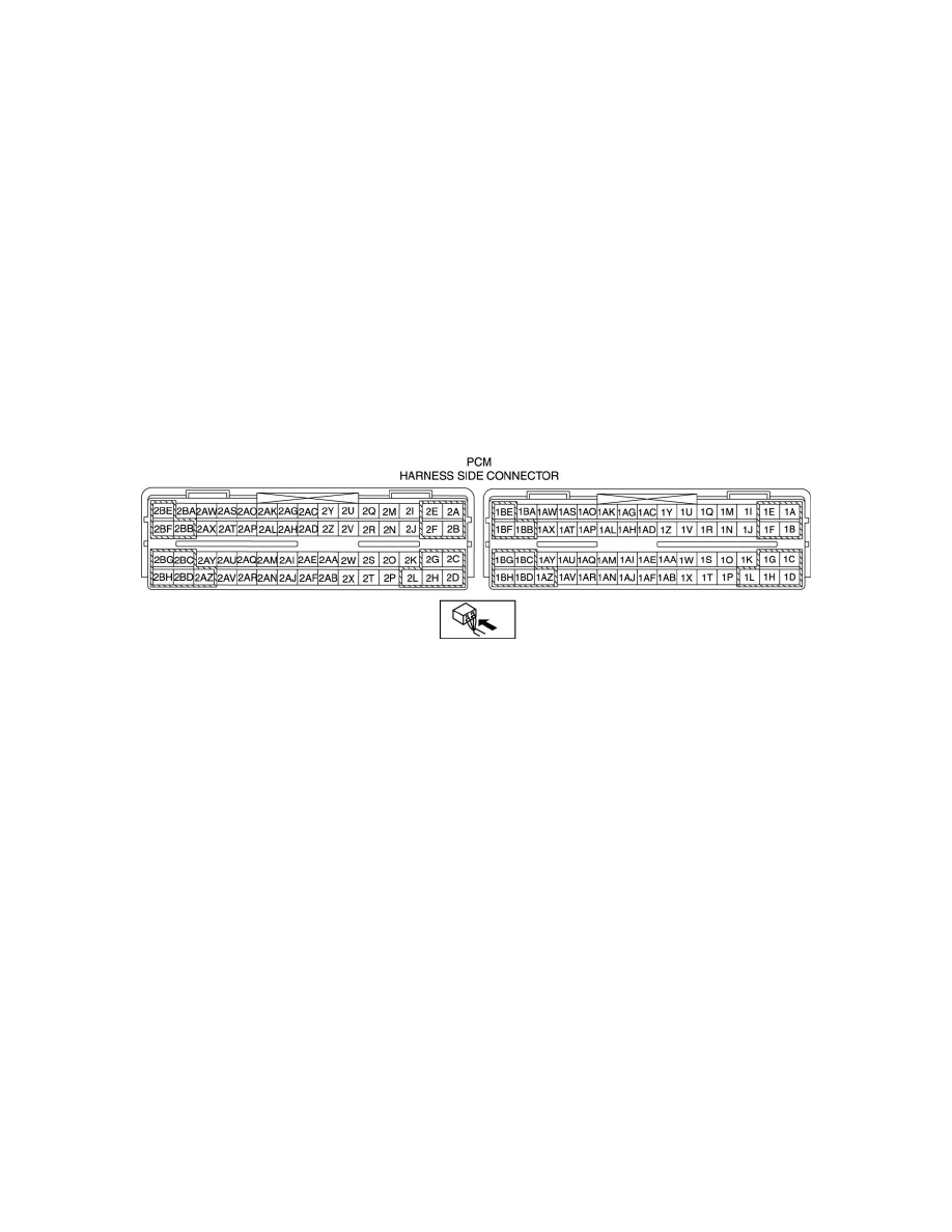
1. Measure the voltage at each terminal.
-
If any incorrect voltage is detected, inspect the related system(s), wiring harnesses and connector(s) referring to the Action column in the
terminal voltage table.
Terminal voltage table (Reference)