
Step 1
- Make
- Mazda
- Model
- MX-5 (NA) Factory Workshop Manual
- Year
- 1990–1992
- Section
- Flowchart No. 6 (T) › Step 1
Body electrical systemStep 1
Caution
• Before troubleshooting, read SERVICE PRECAUTION on page T–133.
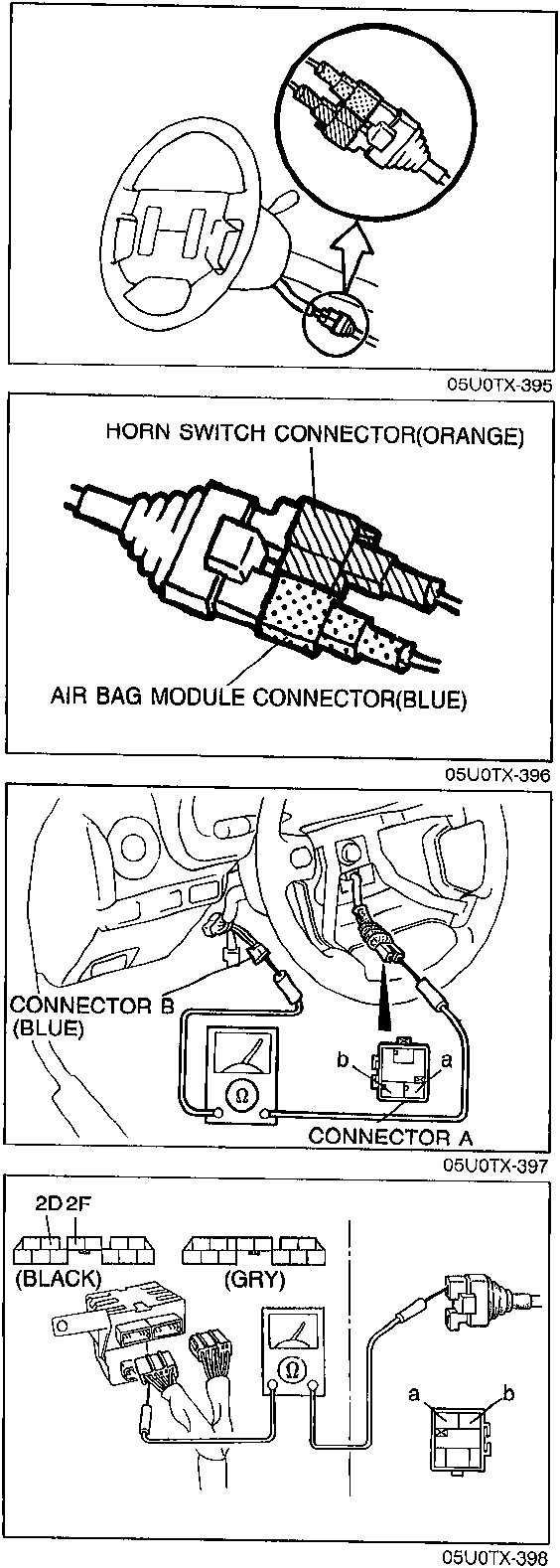
Step 1
- Disconnect the negative battery cable.
- Check for proper connection of the clock spring connectors (Orange and blue).
- If a connector is loose or disconnected, reconnect it.
- If the connections are OK, go to Step 2.
Step 2
- Remove the air bag module installation nuts.
- Verify that the air bag module connector is properly connected.
- If the connector is loose or disconnected, reconnect it.
- If the connection is OK, go to Step 3.
Step 3
- Disconnect the air bag module and clock spring connector.
- Check continuity between terminals of the clock spring connectors (blue) as shown.
| Terminals | Continuity | |
|---|---|---|
| Connector A | Connector B | |
| a | A | Yes |
| b | B | Yes |
- If not as specified, replace the clock spring connector.
Step 4
- Disconnect the diagnostic module connector.
- Check continuity between the diagnostic module connector and the clock spring connector (wire harness side) as shown.
| Terminal-wire | Continuity | |
|---|---|---|
| (Diagnostic __ (Clock spring module) connector) | ||
| (2D : G/W)—(a : R) | Yes | |
| (2F : G/Y)—(b : G/Y) | Yes | |
- If not as specified, replace the wire harness assembly.
4. If correct, go to Step 5.
Parts & tools for this job For 1990 Mazda MX-5
- TOOLDigital multimeterSearch: automotive digital multimeter
- PARTAssorted fuse kitSearch: car fuse assortment kit
- TOOLWire crimper and connector kitSearch: wire crimper connector kit
Links open Amazon search results in a new tab. As an Amazon Associate I earn from qualifying purchases.