
Sable V6-183 3.0L DOHC VIN S MFI (1997)
PURPOSE
Check the lift of each lobe in consecutive order and make a note of the readings.
PROCEDURE
1. Remove valve covers (6582).
2. Remove spark plugs.
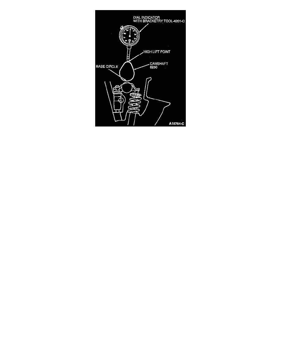
3. Install Dial Indicator with Bracketry TOOL-4201-C or equivalent so that the rounded tip of the indicator is on top of camshaft lobe and on the
same plane as valve tappet.
NOTE: Crank engine with ignition switch in OFF position.
4. Connect an auxiliary starter switch in starting circuit. Bump crankshaft (6303) over until valve tappet is on base circle of camshaft lobe. At this
point, camshaft lobe will be in its lowest position. If checking during engine assembly, turn crankshaft using a socket wrench and/or ratchet.
5. Zero the dial indicator.
6. Continue to rotate crankshaft slowly until camshaft lobe is in fully-raised position (highest indicator reading). Record reading.
7. To check accuracy of original indicator reading, continue to rotate crankshaft until indicator reads zero.
NOTE: If lift on any lobe is below specified service limits, camshaft and valve tappet operating on worn lobes must be replaced, as well as any
flat valve tappet showing pitting or a worn or concave contact face. Roller valve tappets showing wear on roller or having damaged bearings must
be replaced.
8. Compare total lift recorded with specifications.
9. Repeat procedure for each lobe.
10. Remove dial indicator, adapter and auxiliary starter switch.
11. Install valve covers.
12. Install spark plugs.
OFF VEHICLE