
Sable V6-183 3.0L DOHC VIN S MFI (1997)
Rocker Arm Assembly: Service and Repair
NOTE: Ford does not provide a TDC (Top Dead Center) mark or determination procedure for this engine in this vehicle.
REMOVAL
1. Remove upper intake manifold See: Intake Manifold/Service and Repair
and valve covers. See: Valve Cover/Service and Repair
2. Remove crankshaft pulley. See: Cylinder Block Assembly/Harmonic Balancer - Crankshaft Pulley/Service and Repair
3. Remove crankshaft damper retaining bolt from front of crankshaft allowing key way to be referenced.
4. CAUTION:Rotate crankshaft clockwise to position the crankshaft keyway to the 11 o'clock position and engine to top dead center (TDC)
No. 1 cylinder prior to removal and installation of camshafts and rocker arms or damage to camshafts may occur.
Rotate crankshaft clockwise to top dead center (TDC) No. 1 cylinder.
5. Verify the alignment flags (marked RFF) on the camshafts are aligned. If the arrows on the camshaft are not aligned, rotate the crankshaft
clockwise one complete revolution.
6. Rotate crankshaft clockwise to position crankshaft keyway to the 3 o'clock position. This will position the RH cylinder head camshafts to the
neutral position (base circle).
7. CAUTION:Cylinder head camshaft journal caps and cylinder heads should be identified to verify that they are assembled in their
original position. When removed, keep camshaft journal caps from each cylinder head with the head they were removed from. Do not mix
with camshaft journal caps from another cylinder head.
CAUTION:Remove cylinder head camshaft journal thrust cap first to ensure that damage to the cylinder head camshaft journal thrust
cap does not occur.
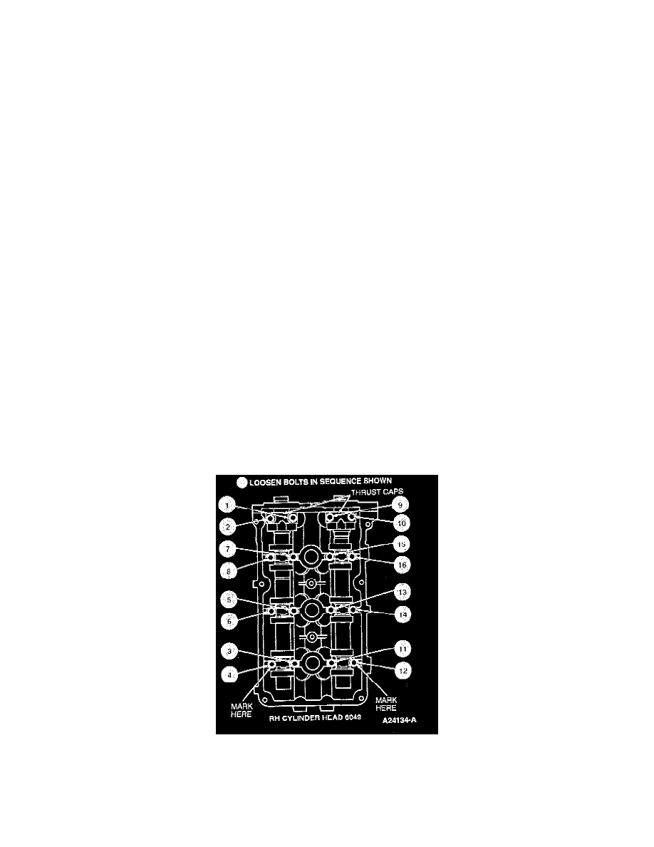
Remove cylinder head camshaft journal thrust cap retaining bolts and thrust caps from RH cylinder head.
8. Loosen remaining RH cylinder head camshaft journal cap bolts 7-8 turns in sequence shown in several passes (approximately 1-2 turns each pass)
to allow camshafts to be raised from RH cylinder head. Do not remove retaining bolts completely.
9. CAUTION:If roller rocker arms are to be reused, mark position of rocker arms to verify that they are assembled in their original
positions.
With RH cylinder head camshaft journal caps and camshafts loose on RH cylinder head, remove rocker arms.
10. Rotate crankshaft and position crankshaft keyway to the 11 o'clock location. This will position the LH cylinder head camshafts to neutral position