
Villager V6-181 3.0L SOHC VIN 1 EFI (1997)
NOTE: When removing the RH front wheel driveshaft joint, it is not necessary to remove the front axle bearing retainer bracket from the cylinder
blocks.
19. Pull the RH front wheel driveshaft joint from the differential side gear.
20. Support the front wheel driveshaft and joints and slide them out of the vehicle. Be careful not to damage the front wheel driveshaft joint boots.
Place the front wheel driveshaft and joints on a flat, protected work area.
21. If servicing any component on the front wheel driveshaft and joints, refer to that part.
INSTALLATION
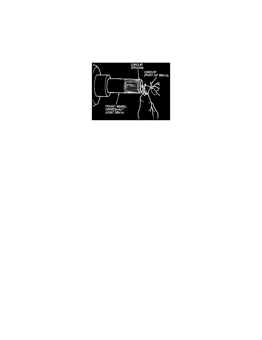
1. If servicing the LH front wheel driveshaft and joint, install a new circlip on the front wheel driveshaft joint.
CAUTION: Do not reuse the original circlip.
NOTE: To prevent over-expanding the circlip install the circlip by starting one end of the circlip in the shaft groove and working the circlip over
the front wheel driveshaft joint end.
2. Inspect the front wheel driveshaft joint boots and ensure that the proper type and amount of lubricant is used on the front wheel driveshaft joints.
3. Inspect the differential oil seals. If they show any sign of damage, replace them.
4. If installing the LH front wheel driveshaft and joint, position the front wheel driveshaft joint so the joint splines are aligned with the differential
side gear splines, then push the front wheel driveshaft joint into the transaxle case. As the circlip locks into the differential side gear groove, a
click will be felt.
5. To install the RH front wheel driveshaft and joint, push the front wheel driveshaft joint into the differential side gear.
NOTE: No circlip is used on the RH front wheel driveshaft joint.
6. Position the front axle bearing retainer on the front axle bearing retainer bracket.
7. Install the three front axle bearing retainer-to-bracket bolts. Tighten the front axle bearing retainer-to-bracket bolts to 13-19 Nm (8-14 ft. lbs.).
8. Position the front wheel driveshaft and joint through the wheel hub.
9. Insert the front suspension lower arm ball joint stud partially through the front wheel knuckle and start the front suspension lower arm ball joint nut
on the stud.
10. Push the front suspension lower arm ball joint completely into the front wheel knuckle. Tighten the front suspension lower arm ball joint nut to
71-86 Nm (52-63 ft. lbs.).
11. Install a new front suspension lower arm ball joint cotter pin.
12. Install the front stabilizer bar link into the front suspension lower arm. Tighten the front stabilizer bar link-to-front suspension lower arm nut to
16-22 Nm (12-16 ft. lbs.).
13. Install the front wheel outer bearing retainer washer and front axle wheel hub retainer. Tighten the front axle wheel hub retainer to 235-314 Nm
(174-231 ft. lbs.).
14. Install a new cotter pin.
15. Position the engine and transmission splash shield and install the seven RH or seven LH engine and transmission splash shield screws. Tighten the
engine and transmission splash shield screws securely.
NOTE: If removed, position the RH front fender inner splash shield and install the six RH front fender inner splash shield screws. Tighten the RH
front fender inner splash shield screws securely.
16. Install the front wheel and tire assembly. Tighten the lug nuts to 98-118 Nm (72-87 ft. lbs.).
17. Lower the vehicle.
18. Check the transmission fluid level.