
Ratio control motor functionality
- Make
- MG
- Model
- MGF Stepspeed EM-CVT Automatic Gearbox Workbook
- Section
- Ratio control motor functionality
2
The E fault bit will be set if the GIU is using stored back up values of configurable data. The general fault bit will be set if the GIU detects an internal failure preventing its control of the ratio control motor.
In order to protect the EMS against serial link failures while reading data when the start bit of a message is received a timer is started. This time is adequate for the delivery of all possible messages. After 60 m/s if the remainder of the message has not been received by the EMS the timer expires and the message is ignored.
Note: Though the GIU sends data about various faults it is not capable of storing faults. This is done by the ECM.
Ratio control motor functionality
The ratio control motor is housed inside the transmission, adjacent to the oil cooler pipe connections . The motor is connected to the main harness via a circular connector. The motor is operational in all transmission modes and controls the hydraulic control unit to adjust the primary pulley to the appropriate position.
Ratio control motor
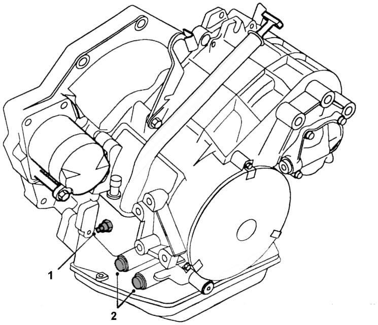
Figure 29
1.Ratio control motor 2.Oil cooler feed/return connections
The EMS produces a pulse width modulated (PWM) output to request the ratio control motor position from the GIU. The output is held high by an internal pull up resistor and pulled down for a period of time to create the signal. The frequency of the PWM supply is 500 Hz which equates to a time period of 2 milliseconds (1 ÷ 500).
Parts & tools for this job For MG MGF
- TOOLOBD2 scannerSearch: OBD2 scanner
- TOOLDigital multimeterSearch: automotive digital multimeter
- TOOLBack-probe test leadsSearch: back probe test leads
Links open Amazon search results in a new tab. As an Amazon Associate I earn from qualifying purchases.