
Steel belt construction
- Make
- MG
- Model
- MGF Stepspeed EM-CVT Automatic Gearbox Workbook
- Section
- Steel belt construction
Torque and speed of the secondary pulley are determined by the position of the drive belt. The sizes of the two pulleys are designed to provide a range of ratios resulting in a ratio spread of 5.454 to 5.763. The high overdrive ratio is particularly advantageous in respect to fuel consumption.
The steel drive belt has approximately 450 segments and is held together by 24 steel bands, 12 on each side. All the segments are of the same thicknesses unlike the earlier transmission (VT1- Rover 100 and 200) which had 350 segments of different thicknesses to prevent high frequencies (belt noise) being generated during operation.
Steel belt construction
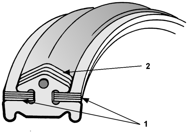
Figure 6
1.Steel bands 2.Steel segments
Note: When handling the steel drive belt always squeeze the perimeter, otherwise it may fall apart. The belt need not be adjusted or replaced in service.
Pinion shaft
The pinion shaft creates a two-set helical gear reduction between the secondary pulley and the crown wheel. In this way, the rotational direction of the driveshafts will be correct. The reduction between the secondary pulley and the driveshafts can be made big enough to give good vehicle performance. The pinion shaft is supported by two conical bearings, one in the clutch housing and one in a separate bearing support.
Differential
Drive torque on the crown wheel is transmitted to the vehicle wheels via a bevel gear differential, just as in a manual transmission. The crown wheel is bolted to the differential case with 8 bolts. The driveshafts are fitted to the differential with conventional CV joints and seals. Conical bearings are used to support the differential.
Parts & tools for this job For MG MGF
- TOOLTorque wrenchSearch: 3/8 inch torque wrench
- TOOLSocket setSearch: socket set metric
- BOOKHaynes manualSearch: Haynes manual MG MGF
Links open Amazon search results in a new tab. As an Amazon Associate I earn from qualifying purchases.