
Engine management (MEMS 3), fuel and emission systems (Ignition Coils): Description and operation
- Make
- MG
- Model
- TF Factory Workshop Manual
- Year
- 2002–2005
- Section
- Description and operation › Ignition Coils
The stepper motor referencing procedure can take from three to five seconds. If the ECM cannot reference the stepper motor during power down, it will do so at ignition on. If the stepper motor fails, there are no back up idle control systems. The idle speed may be too high or too low and if a load is placed on the engine it may stall. The ECM will store fault codes which can be retrieved by TestBook.
Ignition Coils
Two ignition coils are mounted on the camshaft cover above the spark plugs for cylinders 1 and 3 and secured with screws.
Each coil operates a pair of spark plugs using the wasted spark principle. The coil has a plug connection on its lower face and an ht lead which connects to the second plug.
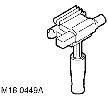
The coil fitted above cylinder 1 is attached to the spark plug for cylinder 1 and the ht lead connects to the spark plug for cylinder 4.
The coil fitted above cylinder 3 is attached to the spark plug for cylinder 3 and the ht lead connects to the spark plug for cylinder 2.
WARNING: The ht voltage of the ignition system is in excess of 50 kV and the lt voltage is in excess of 400 volts. Voltages this high can cause serious injury and may even be fatal. Never touch any ignition components while the engine is running or being cranked.
CAUTION: Never crank or run the engine with the ht leads disconnected from the ignition coils; failure of the ECM and/or the coil will result. Always disable the ignition system by disconnecting the lt connectors from the coil.
Each ignition coil consists of a pair of windings wrapped around a laminated iron core. The primary winding has a resistance of 0.7Ω and the secondary winding has a resistance of 10 kΩ .
Fuel Injectors
The fuel injectors are located directly under the fuel rail and connect to the intake manifold runners. Each injector delivers fuel to the engine in a targeted, atomised spray (onto the intake valve heads) which takes place once per cycle. Each injector opens during the intake stroke of the cylinder it supplies.
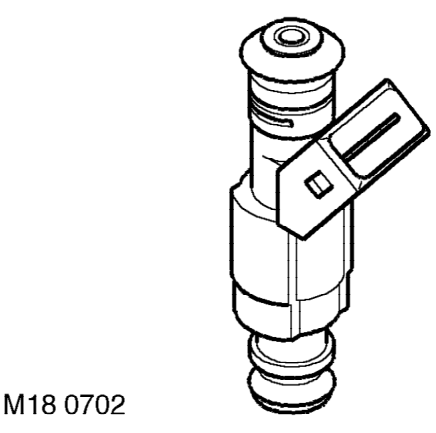
An injector consists of a pintle type needle and seat, and a solenoid winding which lifts the needle against a return spring. The injector nozzle delivers the fuel spray to precise areas of the intake ports to maximise the benefits of the swirl and turbulence in the manifold and head ports.
Parts & tools for this job For 2002 MG TF
- PARTSpark plugsSearch: MG TF 2002 spark plugs
- TOOLSpark plug socketSearch: spark plug socket
- TOOLSpark plug gap toolSearch: spark plug gap tool
Links open Amazon search results in a new tab. As an Amazon Associate I earn from qualifying purchases.