
Eclipse L4-1997cc 2.0L DOHC (1991)
Oil : 0.20-0.70 mm (0.0079- 0.0276 in.)
Limit:
No.1, No.2 : 0.8 mm (0.031 in.)
Oil : 1.0 mm (0.039 in.)
CONNECTING ROD BEARING
1. Visually check the bearing surface for uneven contact, streaks, scratches, and seizure. Replace if defects are evident. If streaks and seizure are
excessive, check also the crankshaft. If damage is present on the crankshaft, replace crankshaft or regrind to undersize for reuse.
2. Measure the connecting rod bearing I.D. and crankshaft pin O.D. if the oil clearance exceeds the limit, replace bearing, and crankshaft if
necessary. Or, regrind the crankshaft to an undersize and replace bearing with an undersize one.
Standard value: 0.02-0.05 mm (0.0008-0.0020 in.)
Limit: 0.1 mm (0.004 in.)
NOTE: For oil clearance measuring method using the plastic gauge, refer to the section CRANKSHAFT.
SERVICE POINTS OF REASSEMBLY
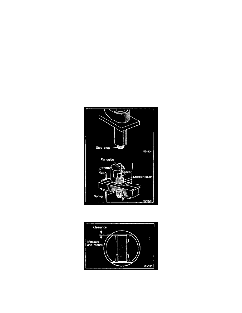
10. INSTALLATION OF PISTON PIN
1. Thread stop plug approximately half way into the bottom of the receiving tube.
2. Select the largest diameter piston pin guide that will pass through piston and rod. install spring, spacer, and guide into receiving tube.
3. With connecting rod removed from piston, insert piston pin into piston bore. Carefully measure amount of pin that protrudes equally from both
sides of piston. Record this measurement for further use.
4. Position connecting rod and piston over the anvil. The spring loaded piston guide will pass through piston and rod and align it. Lubricate pin
and insert it into piston.
5. Place piston pin pusher on piston pin and push pin through connecting rod until the pin protrudes some distance measured and recorded above
in step 3.