
Eclipse L4-1997cc 2.0L DOHC (1991)
Connecting rod: G6
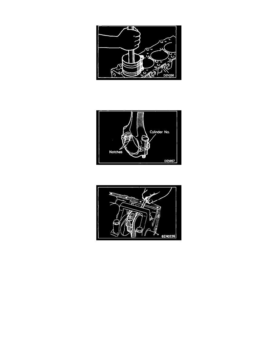
4. With the piston rings held in position with a piston ring compressor, insert the piston and connecting rod assembly. Driving the assembly into
position by using excessive force can result in a damaged piston ring or crankshaft pin.
2. INSTALLATION OF CONNECTING ROD CAP
1. Mate the correct bearing cap with the correct connecting rod by checking with the alignment marks marked during disassembly. If a new
connecting rod is used which has no alignment mark. position the notches for locking the bearing on the same side.
2. Check if the thrust clearance in the connecting rod big end is correct.
Standard value: 0.10-0.25 mm (0.0040-0.0098 in.)
Limit: 0.4 mm (0.0157 in.)