
Eclipse GT V6-3.0L SOHC (2000)
STEP 3. Check the harness wires between ETACS-ECU connector C-114 and ignition switch (ACC).
NOTE: After checking junction block connector C-101, check the wires. If junction block connector C-101 is damaged, repair or replace it. Refer to
Harness Connector Inspection.
If the harness wires between ETACS-ECU connector C-114 and ignition switch (ACC) is damaged, repair them. The ignition switch (ACC) input signal
should be able to be checked and the functions, which are described in the "Technical Description (comment)," should work normally.
Inspection Procedure O-2
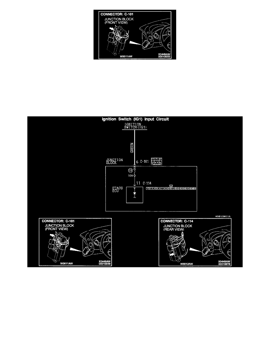
Ignition Switich (IG 1) Input Circuit
CIRCUIT OPERATION
-
The ETACS-ECU operates various functions according to the input signal from the ignition switch (IG1).
-
This circuit will work as a backup circuit if the battery circuit to the ETACS-ECU is open circuited.
TECHNICAL DESCRIPTION (COMMENT)
The ignition switch (IG1) input signal is used to operate the following devices or functions. If the signal fails, these devices will not work normally.
-
Ignition key tone alarm function
-
Light reminder tone alarm function
-
Seat belt tone alarm function
-
Power window timer function