
Lancer L4-2.4L SOHC (2005)
STEP 6. Check the wiring harness between ETACS-ECU connector C-226 (terminal 11) and the battery.
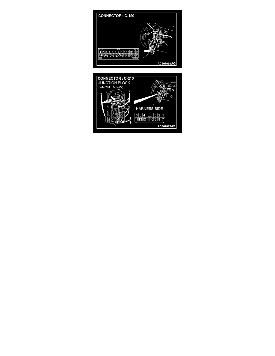
NOTE: Also check intermediate connector C-129 and junction block connector C-210 for loose, corroded, or damaged terminals, or terminals pushed
back in the connector. If intermediate connector C-129 or junction block connector C-210 are damaged, repair or replace the damaged component(s) as
described in Harness Connector Inspection.
Q: Is the wiring harness between ETACS-ECU connector C-226 (terminal 11) and the battery in good condition?
YES: No action is necessary and testing is complete.
NO: The wiring harness may be damaged or the connector(s) may have loose, corroded or damaged terminals, or terminals pushed back in the
connector. Repair the wiring harness as necessary. Verify that the turn-signal lights illuminate normally.
STEP 7. Check the input signal by using "FUNCTION DIAG." menu of the SWS monitor.
Check the input signals from the following switches:
-
Ignition switch: ON
-
Turn-signal light switch: RH
CAUTION: To prevent damage to scan tool MB991958, always turn the ignition switch to the "LOCK" (OFF) position before connecting or
disconnecting scan tool MB991958. Connect the DLC harness before connecting the column-ECU harness. Be sure to connect SWS monitor kit
MB991813 after turning on scan tool MB991958.