
Lancer L4-2.4L SOHC (2005)
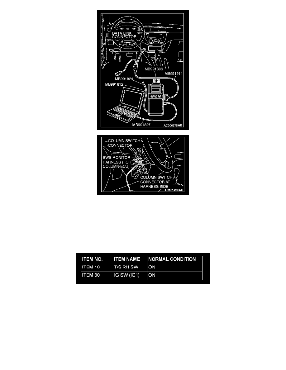
1. Connect scan tool MB991958 to the data link connector.
2. Connect SWS monitor kit MB991813 to the column switch connector.
3. Operate scan tool MB991958 according to the procedure below to display "TURN SIG.RH."
a. Select "SYSTEM SELECT."
b. Select "SWS."
c. Select "SWS MONITOR."
d. Select "FUNCTION DIAG."
e. Select "TURN SIGNAL."
f.
Select "TURN SIG.RH."
4. Check that normal conditions are displayed on the items described in the table.
Q: Are normal conditions displayed on the "T/S RH SW" and "IG SW (IG1)"?
Normal conditions are displayed for all the items : Go to Step 8.
The scan tool does not show the respective normal condition for item "T/S RH SW" : Refer to Inspection Procedure M-5 "ETACS-ECU does
not receive any signal from the turn-signal RH switch."
The scan tool does not show the respective normal condition for item "IG SW (IG1)" : Refer to Inspection Procedure M-2 "ETACS-ECU
does not receive any signal from the ignition switch (IG1)."
STEP 8. Check the input signal by using "FUNCTION DIAG." menu of the SWS monitor.