
Lancer L4-2.4L SOHC (2005)
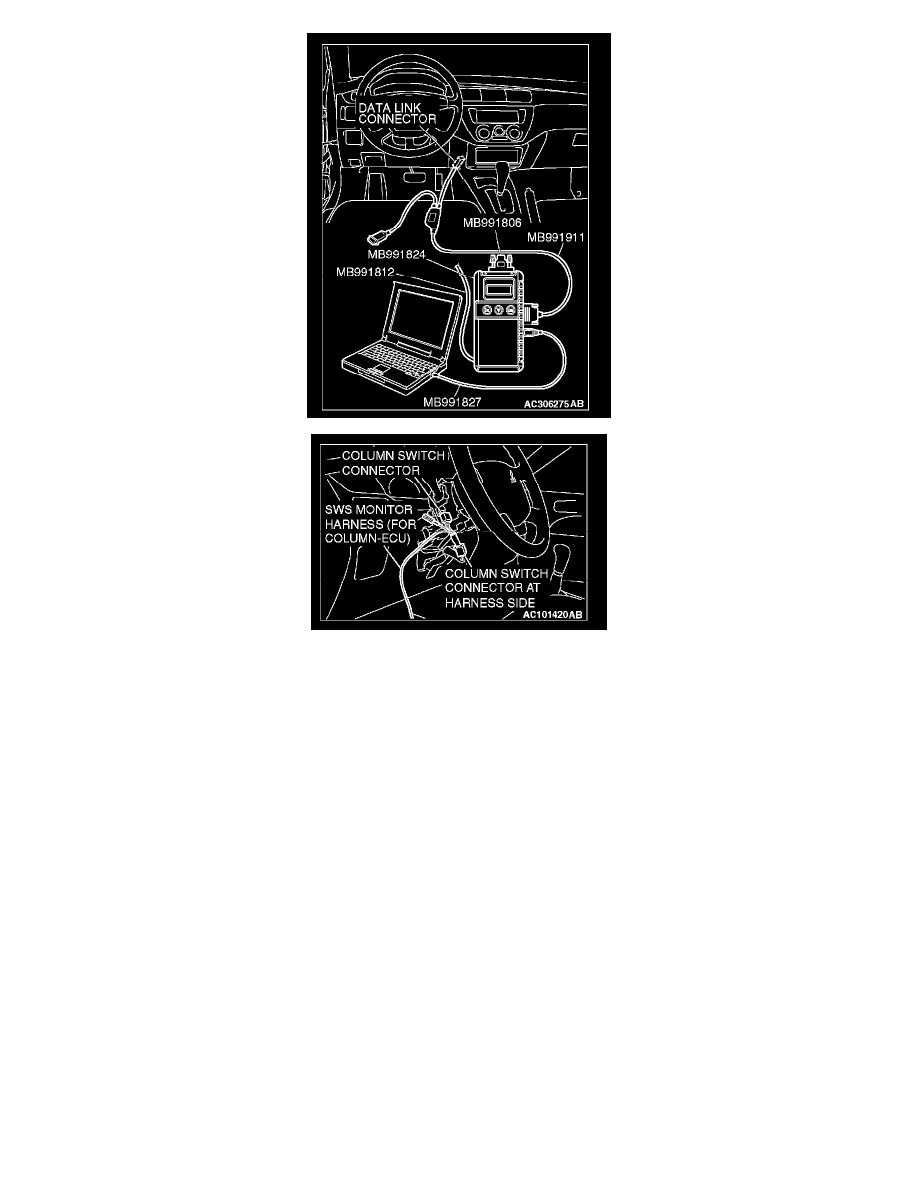
1. Connect scan tool MB991958 to the data link connector.
2. Connect SWS monitor kit MB991813 to the column switch connector.
3. Turn the ignition switch to the "LOCK" (OFF) position.
4. Operate scan tool MB991958 according to the procedure below to display "ECU COMM CHK."
a. Select "SYSTEM SELECT."
b. Select "SWS."
c. Select "SWS MONITOR."
d. Select "ECU COMM CHK."
5. Scan tool MB991958 should show "OK" on the "ECU COMM CHK" menu for the "COLUMN ECU" menu.
Q: Is "OK" displayed on the "COLUMN ECU" menu?
YES: Go to Step 2.
NO: Refer to Inspection Procedure A-2 "Communication with column switch (column-ECU) is not possible."
STEP 2. Replace the ECU.
1. Replace the column switch (turn-signal light and lighting switch).
2. If the functions, which are described in "CIRCUIT OPERATION", work normally, the input signal from the column switch (turn-signal light and
lighting switch) should be normal.
Q: Does the column switch (turn-signal light and lighting switch) send normal signal to the ECU?
YES: No action is necessary and testing is complete.
NO: Replace the ETACS-ECU. If the functions, which are described in "CIRCUIT OPERATION", work normally, the input signal from the
column switch (turn-signal light and lighting switch) should be normal.