
Montero Sport 2WD V6-3.0L SOHC (1997)
Wheel Speed Sensor: Testing and Inspection
Wheel Speed Sensor
Output Voltage Check
1. Lift up the vehicle and release the parking brake.
2. Disconnect the ABS-ECU connector, and then use inspection harness tool No. MB991219 to measure the output voltage at the harness side
connector.
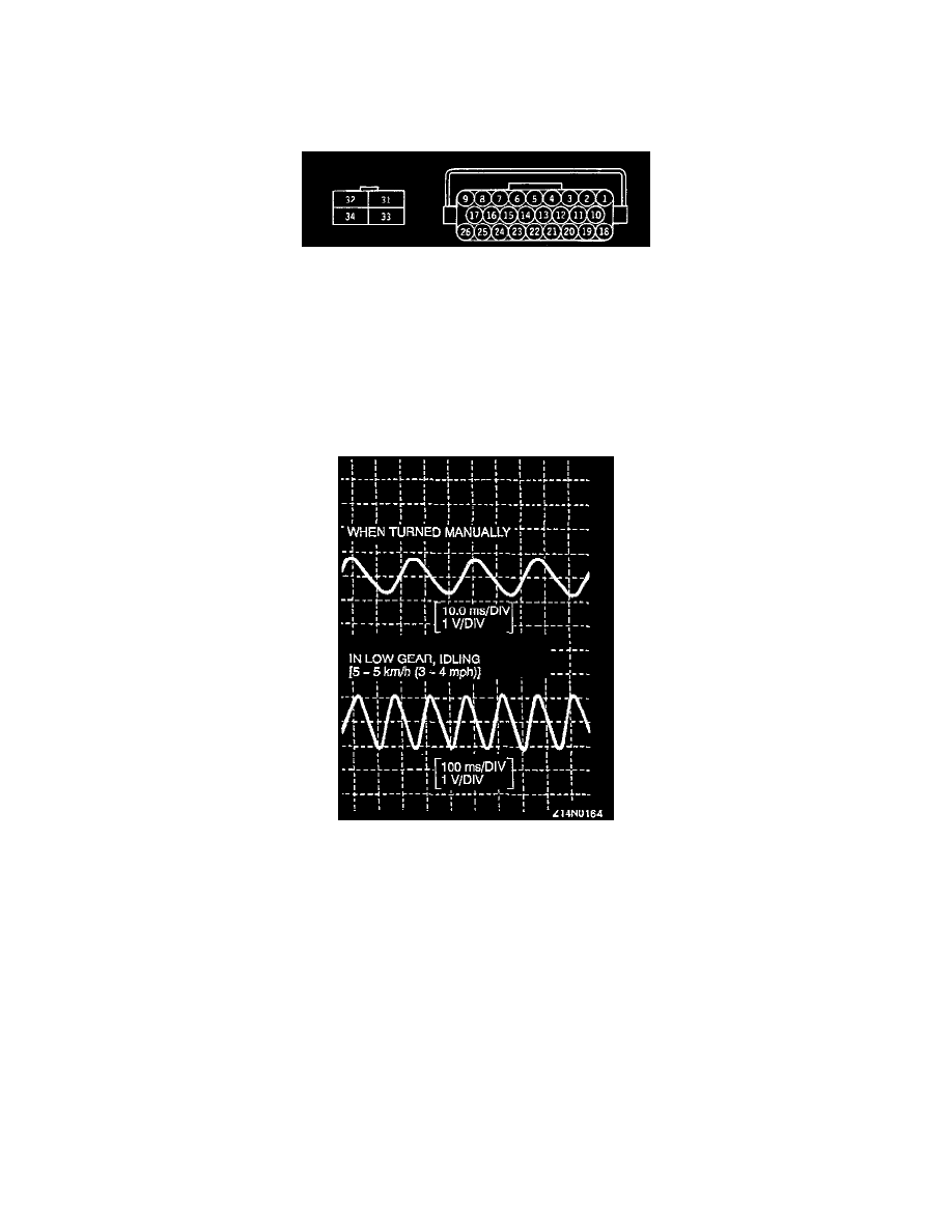
a. The front LH sensor corresponds to terminal Nos. 20 and 21.
b. The front RH sensor corresponds to terminal Nos. 18 and 19.
c. The rear LH sensor corresponds to terminal Nos. 3 and 4.
d. The rear RH sensor corresponds to terminal Nos. 1 and 2.
3. Manually turning the wheel to be measured by 1/2 to 1 turn per second, measure the output voltage with a voltmeter or oscilloscope. The output
voltage when measured with a voltmeter should be 70 mV or more. When measured with oscilloscope (maximum voltage) is 200 mV or more.
4. Probable causes of low output voltage are wheel speed sensor pole piece-to-ABS rotor clearance too large and/or a faulty wheel speed sensor.
Waveform Pattern
NOTE:
-
Waveforms may also be observed by driving the vehicle.
-
The output voltage is low when the wheel speed is low. Similarly, it will be higher as the wheel speed increases.
5. To observe the waveform with an oscilloscope:
For the front wheel sensor observation, shift into low gear and drive the wheels.
NOTE: For the rear wheel sensor observation, turn the wheels manually at a constant speed.