
PB 150 V8-318 5.2L VIN T 2-BBL (1983)
2. Attach a dial indicator to a solid non-rotating portion of the hub assembly or suspension.
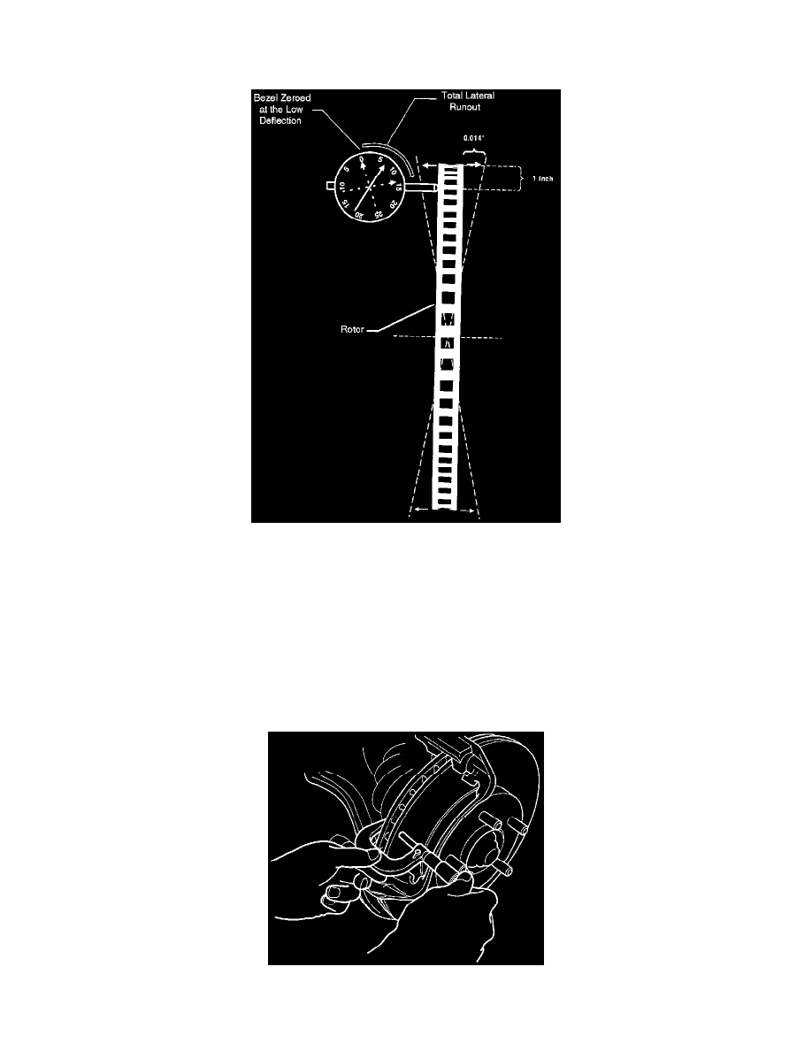
-
The point of the styles must contact the rotor face about 25 mm (1-inch) from the rotor edge.
3. Move the rotor one complete rotation and observe the dial indicator.
4. Rotate the bezel on the dial indicator such that "0" is at the low deflection point.
5. Again rotate the rotor at least one complete turn and observe the needle deflection. Total needle deflection will equal lateral runout.
6. Readjust the wheel bearings.
MINIMUM THICKNESS
The thickness of a rotor is important for two reasons:
1. Rotors which are too thin are not able to properly absorb and release heat during heavy braking. This results in reduced braking capacity and
brake fade.
2. Rotors worn below minimum thickness in combination with worn pads/linings can result in the caliper piston extending too far becoming
cocked or jammed.
Rotor thickness should be measured at the thinnest point on the rotor. Any rotor which is worn below its minimum thickness should be replaced.
For accurate measurements, it is best to remove the caliper to allow for complete access to the inboard side of the rotor.
For more information on how to use a disc brake micrometer see Fundamentals and Basics. See: Fundamentals and Basics