
PB 150 V8-318 5.2L VIN T 2-BBL (1983)
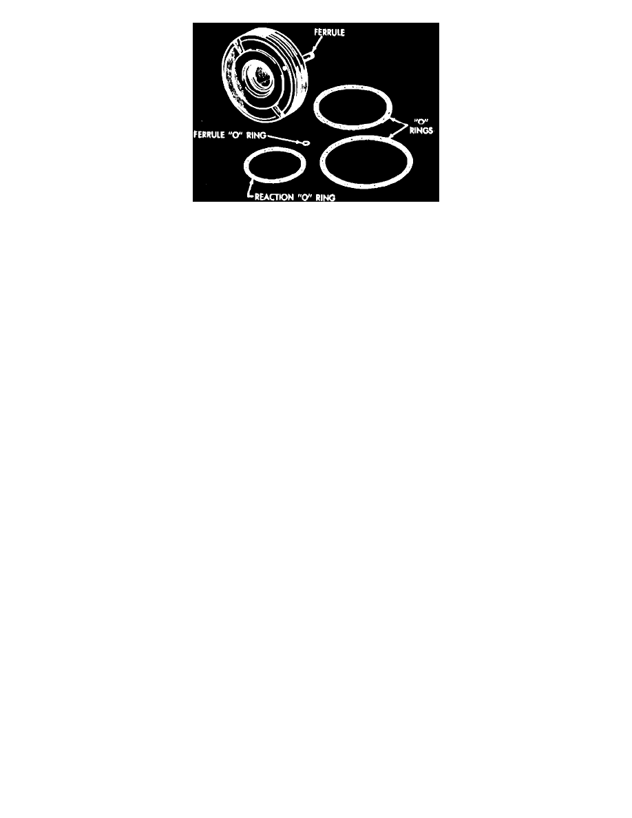
Fig. 6 Cylinder head oil seal ring removal
DISASSEMBLE
1. Place powertrain vertically in a suitable soft jawed vise to prevent damage to piston assembly. To retain 33 worm bearing needle roller bearing
during housing head removal, use arbor tool No. C-3929.
2. Raise housing head until worm shaft oil seal clears top of worm shaft, then position tool No. C-3929 on top of worm shaft and into seal. Raise
housing head until arbor is positioned in bearing, then remove housing head and arbor. bearings become dislodged during head removal,
retain in housing head using a suitable grease for installation. If necessary to replace worm shaft oil seal, perform operation with housing
head installed in gear housing.
3. Remove large O-ring from housing head, then the reaction seal from groove in housing head face by forcing compressed air into ferrule chamber.
4. Remove reaction spring, reaction ring, worm balancing ring and spacer, then retain worm shaft rotation and remove nut from knurled section.
5. Remove thin upper bearing race, then the thrust bearing.
6. Remove center bearing race, then the lower thrust bearing and thick race.
7. Remove lower reaction ring and spring, then the cylinder head assembly.
8. Remove two cylinder head outer groove O-rings, then the reaction O-ring from groove in face of cylinder head by forcing compressed air into oil
hole located between the two O-ring grooves. Remove snap ring and seal.
9. Remove snap ring, sleeve and rectangular oil seal ring from cylinder head counterbore.
10. Ensure torque required to rotate worm shaft throughout its full travel in or out of piston does not exceed 1.5 inch lbs. The worm and piston
assembly are serviced as a complete unit and should not be disassembled.