
911 Carrera Coupe F6-3164cc 3.2L (1984)
Torsion Bar: Service and Repair
Rear Suspension
Refer to ``Trailing Arm Service'' and ``Torsion Bar, Adjust'' procedures.
1.
Raise and support vehicle.
2.
Support radius arm with tool P289.
3.
Remove lower shock absorber retaining bolt.
4.
Remove control arm retaining and eccentric bolts.
5.
Remove radius arm cover retaining bolts.
6.
Remove single spacer.
7.
Pry radius arm cover with two large screwdrivers.
8.
Remove radius arm tool P289.
9.
Remove body plug and the radius arm and torsion bar.
Do not mar torsion bar protective paint.
10.
Reverse procedure to install. Refer to ``Torsion Bar, Adjust''.
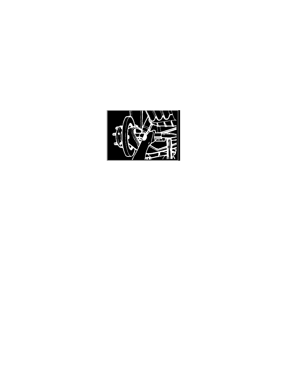
TRAILING ARM SERVICE
Fig. 2 Removing rear wheel hub.
1.
Raise and support vehicle, then remove rear wheels.
2.
Depress brake pedal slightly and hold in position.
3.
Remove brake line between fixed caliper and brake hose.
4.
Remove brake hose clip from rear axle semi-trailing arm, then disconnect brake hose.
5.
Loosen brake caliper attaching bolts and remove caliper.
6.
Loosen countersunk head bolts on brake disc and remove disc.
7.
Support trailing arm with suitable jack and remove shock absorber attaching bolt.
8.
Remove cotter pin from castellated nut and remove nut.
9.
Remove half shaft to joint flange attaching bolts, strike with flat chisel near flange gasket to separate half shaft from joint flange, and remove half
shaft.
10.
Drive out axle shaft toward center of vehicle.
11.
Using tool No. P297a or equivalent, drive out rear wheel hub,
Fig. 2.
12.
Remove cotter pin and castellated nut from brake cable end and pull brake cable out toward center of vehicle.
13.
Unscrew hexagon nut attaching shield plate.
14.
Remove four brake carrier plate attaching nuts and remove brake carrier plate and shield plate.
15.
Disconnect hand brake cable guide.
16.
Remove attaching bolts and nuts and eccentric bolts of rear axle semi-trailing arm flange.
17.
Remove semi-trailing arm pivot bearing attaching nut, then pull out bolt.
18.
Press ball bearing out with suitable press.
19.
Press in new ball bearing with suitable press, applying pressure to bearing outer race.
20.
Install new self locking nut on M14 bolt on trailing arm and torque to 43.2 ft.lbs. while lifting arm until lower edge is level with upper edge of
spring plate.
21.
Torque spring plate retaining bolts to 68.4 ft.lbs. and the camber and toe-in adjustment cams to 43.2 ft.lbs.
22.
Torque hexagon bolts for parking brake support plate and shield plate to 18 ft.lbs.
23.
Tighten hand brake cable castellated nut until cotter pin hole and slot are aligned, then install new cotter pin.
Ensure that expander clip is
positioned correctly.
24.
Using tool No. P298b or equivalent and driveshaft, pull rear wheel hub into radial ball thrust bearing.
Do not use impact wrench to pull wheel
hub into bearings.
25.
Ensure that joint shaft flange surface is smooth and free of grease, then install new gasket and torque M10 Allen screws to 60 ft.lbs. and M8 Allen
head screws to 30.2 ft.lbs.
26.
Torque driveshaft castellated nut to 216-252 ft.lbs. and install new cotter pin.
27.
Torque shock absorber attaching bolts to 90.4 ft.lbs.
28.
Install brake caliper with new spring washers and torque attaching bolts to 43.2 ft.lbs.
29.
Bleed brakes and check for leaks.