
Power distribution
- Make
- Rover
- Model
- 200 Circuit Diagrams
- Year
- 1997 model year
- Section
- Power distribution › Power distribution
Power distributionPower distribution
POWER DISTRIBUTION
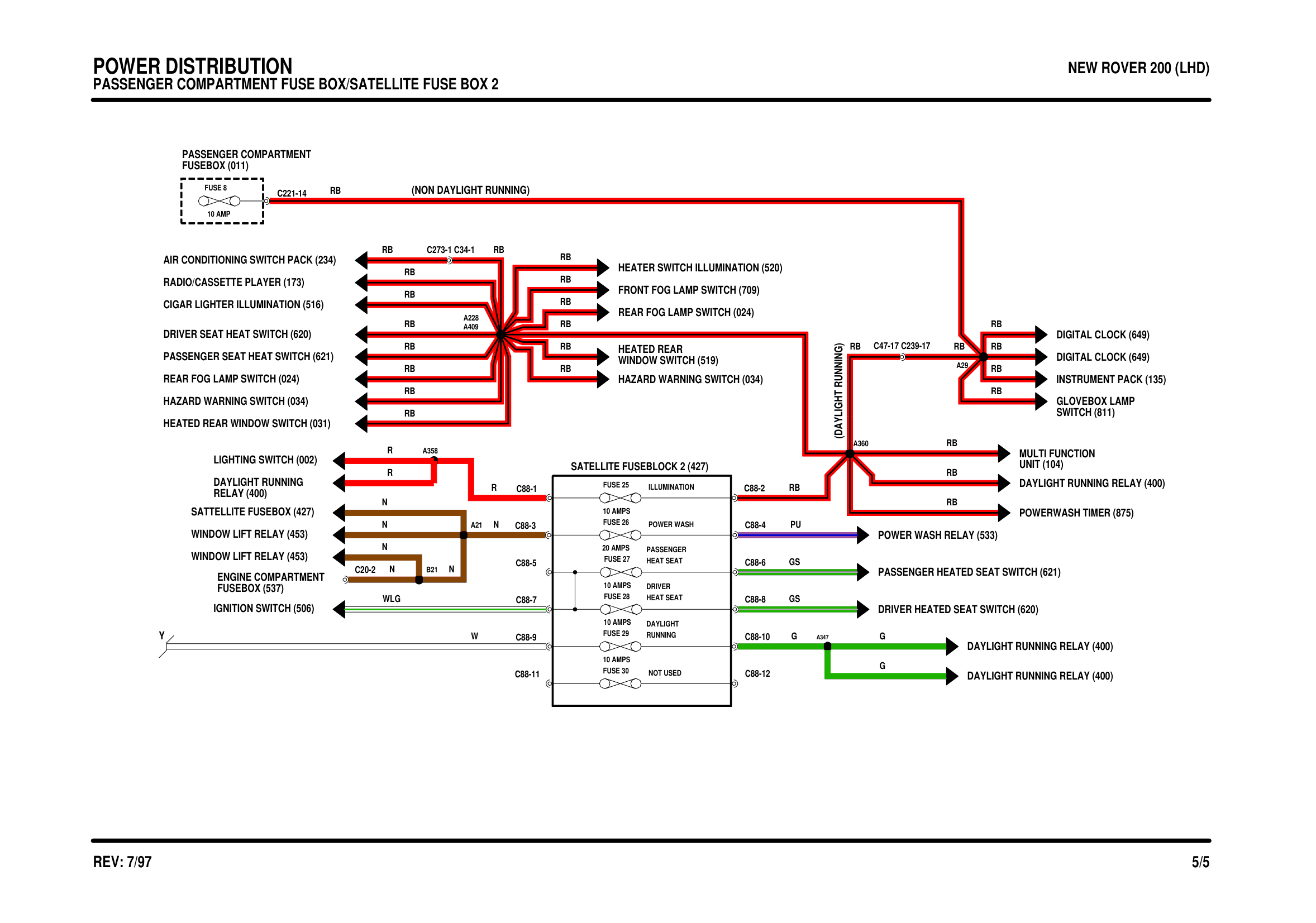
Components on this diagram
- AIR CONDITIONING SWITCH PACK (234)
- CIGAR LIGHTER ILLUMINATION (516)
- DAYLIGHT RUNNING RELAY (400)
- DIGITAL CLOCK (649)
- DRIVER HEATED SEAT SWITCH (620)
- DRIVER SEAT HEAT SWITCH (620)
- FRONT FOG LAMP SWITCH (709)
- FUSEBOX (011)
- FUSEBOX (537)
- HAZARD WARNING SWITCH (034)
- HEATED REAR WINDOW SWITCH (031)
- HEATER SWITCH ILLUMINATION (520)
- IGNITION SWITCH (506)
- INSTRUMENT PACK (135)
- LIGHTING SWITCH (002)
- PASSENGER HEATED SEAT SWITCH (621)
- PASSENGER SEAT HEAT SWITCH (621)
- POWER WASH RELAY (533)
- POWERWASH TIMER (875)
- RADIO/CASSETTE PLAYER (173)
- REAR FOG LAMP SWITCH (024)
- SATTELLITE FUSEBOX (427)
- SWITCH (811)
- UNIT (104)
- WINDOW LIFT RELAY (453)
- WINDOW SWITCH (519)
Parts & tools for this job For 1997 Rover 200
- TOOLTorque wrenchSearch: 3/8 inch torque wrench
- TOOLSocket setSearch: socket set metric
- BOOKHaynes manualSearch: Haynes manual Rover 200
Links open Amazon search results in a new tab. As an Amazon Associate I earn from qualifying purchases.