
Electrical (Headlamps adjust): Adjustments
- Make
- Rover
- Model
- 200 Workshop Manual
- Year
- 1995–1999
- Section
- Adjustments › Headlamps adjust
‹ Prev Electrical components - behind fascia/centre consoleNext › Auxiliary drive belt - ’k’ series with air conditioning
ElectricalHeadlamps adjust
HEADLAMPS ADJUST
Service repair no - 86.40.17
Inspect
- Align suitable beam setting equipment to headlamp. 97.5 MY on: If necessary, set headlamp levelling switch to zero, turn starter switch to position ’II’ and allow headlamps to reset. Turn ignition off.
- Switch on headlamps. Headlamp setting = 1.2% below horizontal and parallel.
Adjust
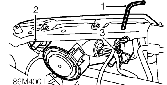
- Adjust headlamp using a 6 mm Allen key.
- Turn Allen screw for vertical alignment.
- Turn Allen screw for horizontal alignment.
- Align beam setting equipment to 2nd headlamp.
- Adjust 2nd headlamp as detailed in steps 1 to 3 above.
- Switch off headlamps.
- Remove beamsetter.
AUXILIARY DRIVE BELT - ’K’ SERIES WITHOUT AIR CONDITIONING
Service repair no - 86.10.05
Check
- Check condition of drive belt, renew a drive belt that shows signs of wear and splitting.
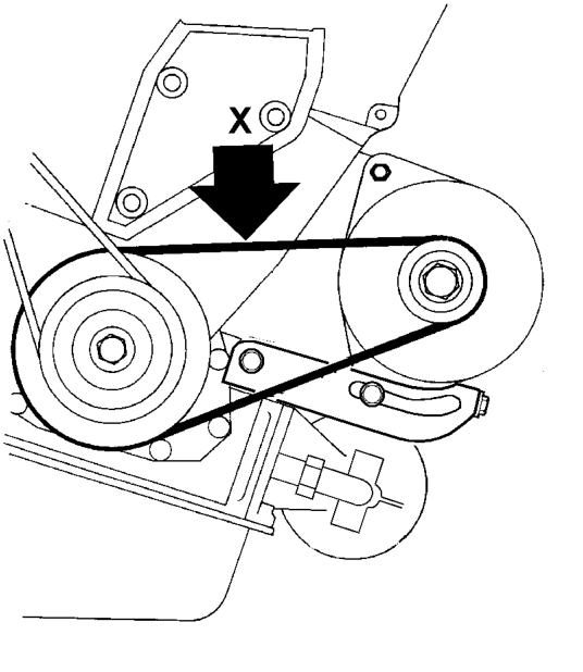
- Apply a force of 10 kg to the drive belt at position ’X’ and measure the deflection between the crankshaft pulley and alternator pulley. Deflection must be 6 - 8 mm.
‹ Prev Electrical components - behind fascia/centre consoleNext › Auxiliary drive belt - ’k’ series with air conditioning
Parts & tools for this job For 1995 Rover 200
- PARTReplacement bulbsSearch: Rover 200 1995 bulbs
- TOOLDigital multimeterSearch: automotive digital multimeter
Links open Amazon search results in a new tab. As an Amazon Associate I earn from qualifying purchases.