
Rear wheel alignment (Steering)
- Make
- Rover
- Model
- 200 Workshop Manual
- Year
- 1995–1999
- Section
- Adjustments › Rear wheel alignment
REAR WHEEL ALIGNMENT
Service repair no - 57.65.06
Check
- Ensure tyre pressures are correct and vehicle is at unladen weight.
- Roll vehicle backwards and forwards to relieve stresses in suspension.
NOTE: Only use equipment recommended in the STEP (Service Tools and Equipment Programme) Manual.
- Ensure that equipment is properly calibrated and take an average of 3 readings.
- Check rear wheel alignment is within tolerance.
NOTE: The following settings are given in A - degrees and minutes, B - decimal parts of a degree and C - millimetres. Settings are for a vehicle at unladen weight.
DATA - EXCEPT BRM:
Rear wheel alignment - toe-in - per side: A- 0° 8’ ± 0° 10’ B- 0.13° ± 0.21° C- 5J x 14 wheel = 0.82 mm1 ± 1.03 mm C- 5 /2 J x 15 wheel = 0.88 mm ± 1.10 mm
Camber - negative: A- 0° 20’ ± 0° 10’ B- 0.33° ± 0.21° C- 5J x 14 wheel = 2.10 mm1 ± 1.03 mm C- 5 /2 J x 15 wheel = 2.20 mm ± 1.10 mm
DATA - BRM:
Rear wheel alignment - toe-in - per side: A- 0° 8’ ± 0° 7.5’ B- 0.13° ± 0.12° C- 0.93 mm ± 0.85 mm
Camber - negative: A- 0° 20’ ± 0° 45’ B- 0.33° ± 0.75° C- 2.41 mm ± 5.32 mm
Adjust
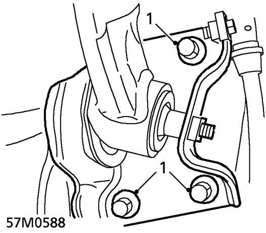
- Loosen 3 bolts securing LH ’H’ frame mounting bracket to body.
- Adjust ’H’ frame in the required direction to achieve correct wheel alignment. If LH wheel value is greater than RH, move LH side of ’H’ frame rearwards. If LH wheel value is less than RH, move LH side of ’H’ frame forwards.
CAUTION: Take care to avoid damaging wheel arch.
- Maintain force on ’H’ frame and tighten bolts, mounting bracket to body, to 100 Nm.
- Recheck rear wheel alignment.
- Repeat steps 1 to 4 if alignment is not within specific tolerances.
Parts & tools for this job For 1995 Rover 200
- TOOLTie rod end toolSearch: tie rod end puller
- TOOLBall joint separatorSearch: ball joint separator
- FLUIDPower steering fluidSearch: Rover power steering fluid
Links open Amazon search results in a new tab. As an Amazon Associate I earn from qualifying purchases.