
Information: Special tools
- Make
- Rover
- Model
- 600 Rover 600 Repair Manual - Volumes 1 and 2 - 2nd Edition
- Section
- Information › Special tools
Drive shaftsSpecial tools
SPECIAL TOOLS
| No. | Honda Number | Rover Number | Description |
|---|---|---|---|
| 1 | 07GAD – PH70201 | 18G 1291/4 | Oil Seal Driver |
| 2 | 07GAF – SD40700 | 18G 1679 | Hub Dis/Assembly Base |
| 3 | 07MAC – SL00100 | 18G 1707 | Ball Joint Remover, 32 mm |
| 4 | 07746 – 0010200 | 18G 1533 | Attachment, 37 x 40 mm |
| 5 | 07746 – 0010400 | 18G 1354 – 5 | Attachment, 52 x 55 mm |
| 6 | 07746 – 0030400 | 18G 1676 | Attachment, 35 mm I.D. |
| 7 | 07749 – 0010000 | 18G 1354 | Driver |
The tools illustrated in this section are Honda tools, and Rover do not always have an equivalent. Where an equivalent Rover tool is available, it may not be visually identical to the Honda tool.
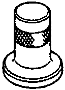
- Oil Seal Driver
- Hub Dis/Assembly Base
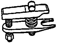
- Ball Joint Remover, 32 mm
- Attachment, 37 x 40 mm
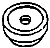
- Attachment, 52 x 55 mm
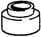
- Attachment, 35 mm I.D.
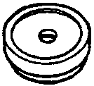
- Driver
47M0102
Parts & tools for this job For Rover 600
- PARTWheel bearingSearch: Rover 600 wheel bearing
- TOOLBearing puller kitSearch: wheel bearing puller kit
- PARTCV boot kitSearch: Rover 600 cv boot kit
Links open Amazon search results in a new tab. As an Amazon Associate I earn from qualifying purchases.