
Jacking, supporting and towing
- Make
- Rover
- Model
- Coupé, Cabriolet & Tourer 200/400 Coupé, Cabriolet & Tourer Workshop Manual
- Section
- Contents › Jacking, supporting and towing
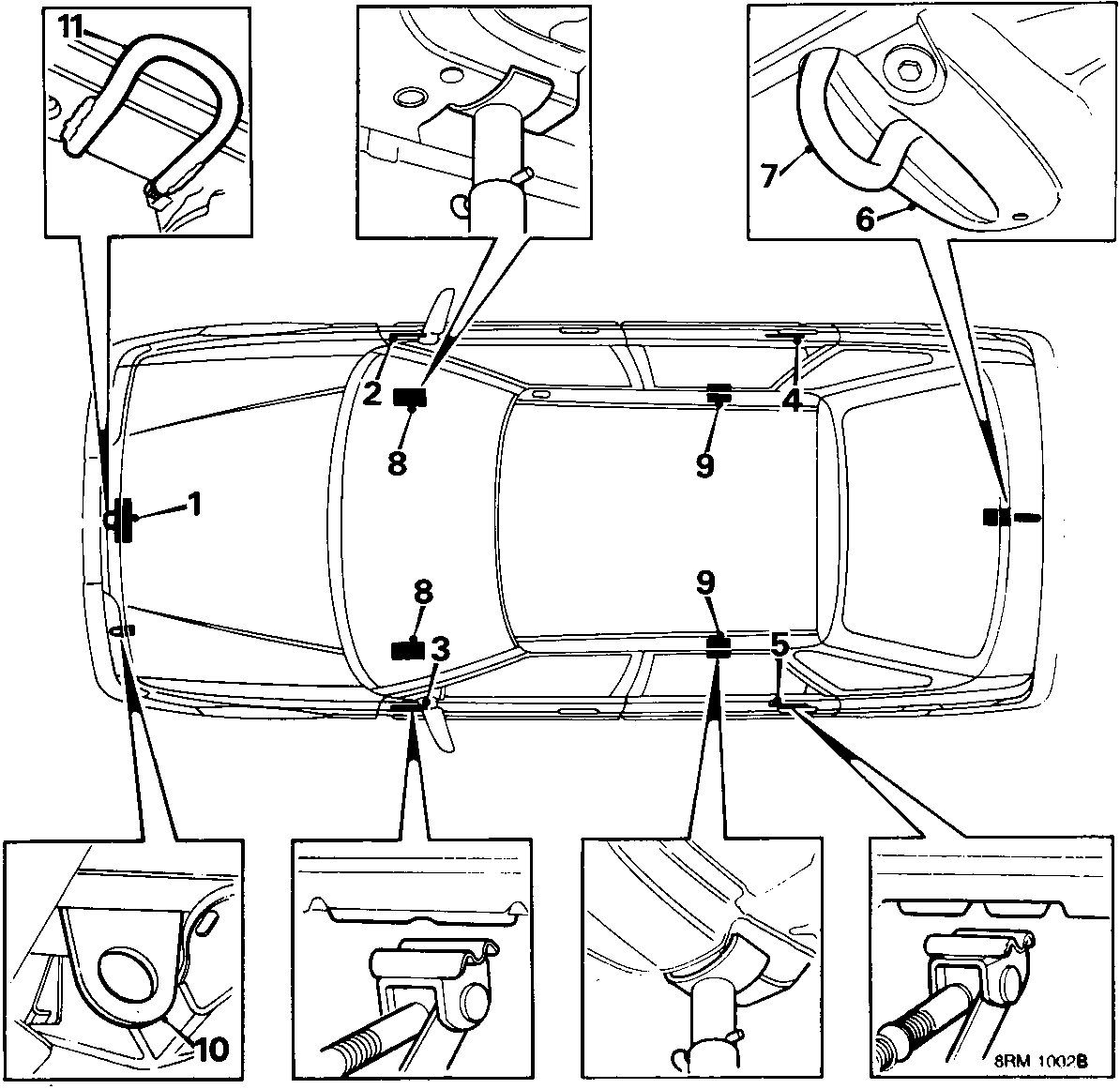
JACKING, SUPPORTING AND TOWING
WARNING: In accordance with normal workshop practice, and to avoid the possibility of damage or personal injury, work must not be carried out on or under a vehicle when it is supported solely on a jack. Place safety supports under the sill reinforced jacking areas (2, 3, 4 or 5).
CAUTION: On models fitted with extended sill finishers, access to the rear jacking areas is partially obscured. Remove the access panel from the finisher prior to positioning the safety support.
WARNING: Do not position a jack, jack stand or wheel free support under the suspension attachment points.
WORKSHOP JACK
Front: Locate the jack head under the central location pad (1).
Position safety supports under both longitudinals (8) or sill reinforced areas (2 and 3).
Rear: Locate the jack head under the reinforced location pad (6) immediately in front of the towing eye (7).
Position safety supports under both longitudinals (9) or remove the access panel from the sill finisher (if fitted) and place safety supports under sill reinforced areas (4 and 5).
Side: Locate the jack head pad under the reinforced area (2 or 3) of the sill and position safety support under longitudinal (8), remove the access panel from the sill finisher (if fitted) and jack under reinforced area (4 or 5) of the sill then position safety support under longitudinal (9).
CAUTION: Do not attempt to jack under suspension attachment points.
Parts & tools for this job For Rover Coupé, Cabriolet & Tourer
- TOOLTorque wrenchSearch: 3/8 inch torque wrench
- TOOLSocket setSearch: socket set metric
- BOOKHaynes manualSearch: Haynes manual Rover Coupé, Cabriolet & Tourer
Links open Amazon search results in a new tab. As an Amazon Associate I earn from qualifying purchases.