
Leon Mk1
| Drive and mechanism cables: disassembly and reassembly; general assembly diagram |
 Note!
Note!| Lubricate the points of support and the sliding surfaces with grease -G 052 142 A2-. |
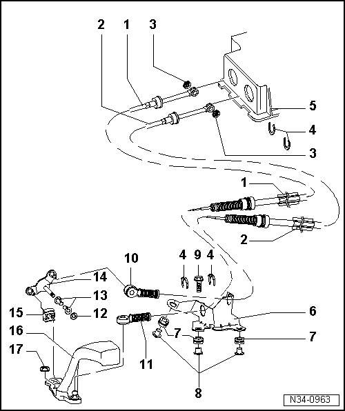
| 1 - | Connection cable for gear |
| q | Fit into the gear lever guide |
| q | Installation position → Chapter |
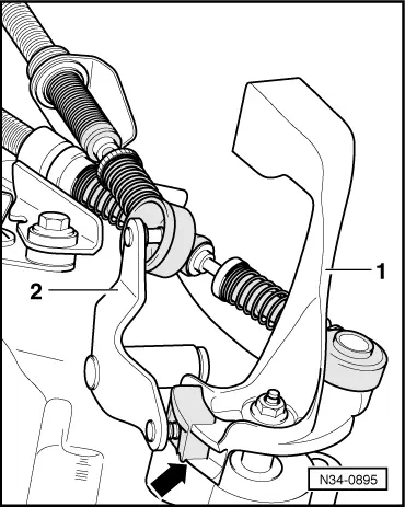
| 2 - | Track selection cable |
| q | It connects to the selector bracket |
| q | Installation position → Chapter |
| 3 - | Spring washer |
| 4 - | Spring washer |
| q | Do not damage the cables when taking it apart |
| 5 - | Gear stick protective cover |
| 6 - | Counter support |
| 7 - | Sleeve |
| q | Support for the counter support in the gearbox |
| 8 - | Spacer piece |
| 9 - | Hexagon bolt |
| q | 25 Nm |
| q | For counter support |
| 10 - | Cable attachment |
| q | To attach the track selection cable to the return lever |
| q | Always replace when it is removed from the return lever |
| 11 - | Cable attachment |
| q | To attach the gear connection cable to the selection rod |
| q | Always replace when it is removed from the selection rod |
| 12 - | Spring washer |
| 13 - | Bearing bush |
| 14 - | Return lever |
| q | Installation position → Fig. |
| 15 - | Guide runner |
| 16 - | Selection rod |
| q | With counterweight |
| q | Insert so that the discontinuous too-thing coincides with the selector rod |
| q | Installation position → Fig. |
| q | Once assembled, adjust the gear drive mechanism → Chapter |
| 17 - | Hexagon nut |
| q | 25 Nm |
|
|