
Leon Mk1
| Gearbox casing and clutch casing: repair |
| Assembly chart |

| 1 - | Gearbox casing |
| q | In the event of replacement, see adjustment chart → Chapter |
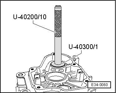
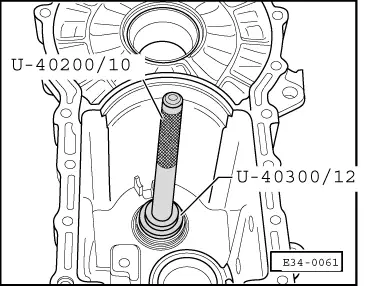
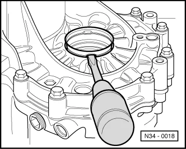
| 2 - | Secondary shaft needle bearing |
| q | For secondary shaft |
| q | Dismount → Fig. |
| q | Assemble and fix into place → Fig. |
| 3 - | Lid for control of oil level. 25 Nm |
| q | Without magnet |
| 4 - | Primary shaft needle bearing |
| q | In the event of replacement, see adjustment chart → Anchor |
| 5 - | Outer track, tapered roller bearing for main shaft |
| q | Dismount and assemble → Chapter |
| q | In the event of replacement, see adjustment chart → Chapter |
| 6 - | Outer track, tapered roller bearing for secondary shaft |
| q | Dismount and assemble → Chapter |
| q | In the event of replacement, see adjustment chart → Chapter |
| 7 - | Adjustment washer for secondary shaft |
| q | In the event of replacement, see adjustment chart → Anchor |
| 8 - | Outer track, tapered roller bearing for main shaft |
| q | Dismount and assemble → Chapter |
| q | In the event of replacement, see adjustment chart → Chapter |
| 9 - | Axial/radial needle bearing for reverse gear axle |
| q | Dismount and assemble → Chapter |
| 10 - | Centring bushes |
| q | 2 units |
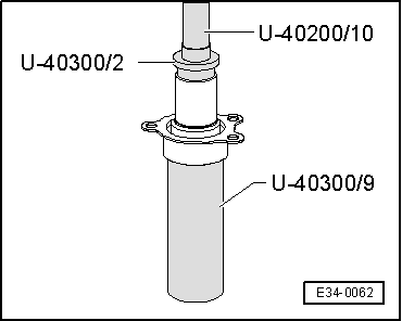
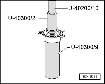
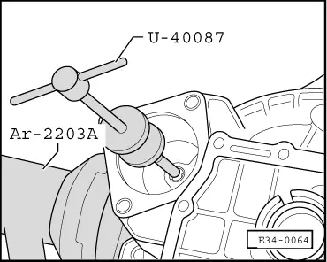
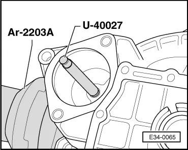
| 11 - | Bush-bearing for the start motor |
| q | Remove → Fig. |
| q | Assemble → Fig. |
| q | It may be replaced with the gearbox mounted. |
| 12 - | Clutch casing |
| q | In the event of replacement, see adjustment chart → Chapter |
| 13 - | Guide sleeve |
| q | With retainer for main shaft and vulcanised O-ring seal |
| q | Dismount → Fig. |
| q | Assemble → Fig. |
| q | In order to replace the retainer for the main shaft it is necessary that the guide sleeve be dismounted. |
| q | Replace the guide sleeve if the O-ring seal is damaged. |
| 14 - | Bolt for attaching the guide sleeve. 20 Nm |
| q | Self-blocking |
| q | Always replace |
| q | Tightening torque: 20 Nm |
| 15 - | Retainer for right coupling flange |
| q | Replacement with the gearbox mounted in the vehicle → Chapter |
| 16 - | Plate sleeve |
| q | For coupling flange retainer → Item |
| q | Dismount → Fig. |
| q | Assemble → Fig. |
| 17 - | Shaft for operating speedometer 30 Nm |
| 18 - | Top for emptying oil. 25 Nm |
| q | Without a magnet |
| 19 - | Outer track for the tapered roller bearing in the differential |
| q | Dismount and assemble → Fig. |
| q | In the event of replacement, adjust the differential → Chapter |
| 20 - | Magnet |
| q | It is held between the casings for the gearbox and the clutch |
| 21 - | Outer track for the tapered roller bearing in the differential |
| q | Dismount and assemble → Fig. |
| q | In the event of replacement, adjust the differential → Chapter |
| 22 - | Adjustment washer for differential |
| q | Finding the thickness → |
| 23 - | Retainer for left flange |
| q | Replacement with the gearbox mounted in the vehicle → Chapter |

| Special tools and workshop equipment required |
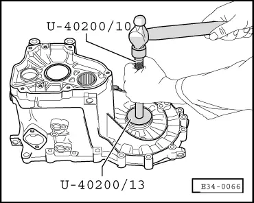
| t | Gearbox repairs case -U-40200- |
| t | Gearbox repairs case -U-40300- |
| t | Taps for Ø 11 and Ø 14 with plunger -U-40087- |
| t | Tool for assembling starter sleeve -U-40027- |
| t | Support column for gearbox-differential -AR-2203A- |
|
|
|
|
|
|
|
|
|
|
|
|
|
|