seat Workshop Repair Guides

SEAT Workshop Service and Repair Manuals

Layshaft: adjustment > < Secondary shaft: dismounting and assembling
Secondary shaft: adjustment
   
Secondary shaft: adjustment
Special tools and workshop equipment required
t  Gearbox repair case -U-40200-
t  Gearbox repair case -U-40300-
t  Multi-purpose stand for the -T20020- comparator
t  Dynometric keys -SAT 8010-

Adjust the secondary shaft when any of the following components have been replaced:
   
t  Clutch casing
t  Secondary shaft
t  Tapered roller bearing in the secondary shaft
So as to avoid unnecessary adjustment work, consult the Chart for Adjustment → Chapter.
–  Dismount the outer track of the tapered roller bearing by carrying out the following steps:
–  Assemble the grips -U-40300/17- on the tool -U-40300/16- using its attachment bolts.
–  Place the set of tools on the lower part of the outer track of the tapered roller bearing. Expand the tool -U-40300/16- by tightening the bolt -1-.
–  Turn the nut -2- until extracting the outer track of the tapered roller bearing.
  E35-0029
–  Assemble the outer track of the tapered roller bearing of the secondary shaft, in the clutch casing, with an adjustment washer 0.65 mm thick, using tool -U-40200/10- and tool -U-40200/12-.
–  Put the secondary shaft into its housing in the gearbox casing.
–  Tighten the bolts for attaching the secondary shaft to the gearbox casing.
Tightening torque: 25 Nm + 90º
  E35-0030
–  Place tool -T20020- with a comparator over the clutch casing. Place the end of it over the secondary shaft.
–  Adjust the comparator to “0” with a prior tension of 1 mm.
–  Alternatively move the secondary shaft in the direction of the comparator.
–  Note down the reading obtained on the comparator. Example, 0.30 mm.
  Note!
When taking the measurement do not turn the secondary shaft. The tapered roller bearings do not settle and they give a false reading.
Calculating the adjustment washer
The thickness of the adjustment washer to be mounted is found by adding the reading values obtained with the comparator, the thickness of the adjustment washer mounted earlier and a set value.
Example:
  E35-0042
Reading obtained with the comparator0.30 mm
Thickness of the washer already mounted0.65 mm
Set value0.20 mm
Thickness of the adjustment washer needed1.15 mm

The adjustment washer needed is to be found using the following Table:
Adjustment Table
   
Thickness (mm)Spare No.
0.65
0.70
020 311 391 P
020 311 391 Q
0.75
0.80
0.85
020 311 391
020 311 391 A
020 311 391 B
0.90
0.95
1.00
020 311 391 C
020 311 391 D
020 311 391 E
1.05
1.10
1.15
020 311 391 F
020 311 391 G
020 311 391 H
1.20
1.25
1.30
020 311 391 J
020 311 391 K
020 311 391 L
1.35
1.40
020 311 391 M
020 311 391 N 

The diversity of the adjustment washers available allows you to find exactly the right thickness needed to perform a proper adjustment of the secondary shaft.
   
–  Should the thickness of the adjustment washer needed be thicker than the thicknesses that appear in the Table, two adjustment washers may be fitted, the thicknesses for which when added together, correspond to the reading required.
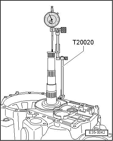
–  Once the adjustment washer needed has been determined, remove the comparator.
–  Separate the secondary shaft.
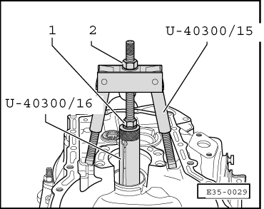
–  Dismount the outer track for the tapered roller bearing by carrying out the following steps:
–  Assemble the grips -U-40300/17- on the tool -U-40300/16- using its attachment bolts.
–  Place the set of tools on the lower part of the outer track of the tapered roller bearing. Expand the tool -U-40300/16- by tightening the bolt -1-.
–  Place the extractor tool -U-40300/15- on the clutch casing and tighten the axle of the extractor into the tool-U-40300/16-.
–  Turn the nut -2- until extracting the outer track of the tapered roller bearing.
–  Remove the washer that is 0.65 mm thick.
  E35-0029
–  Place the adjustment washer with the thickness calculated. Example, 1.15 mm, in the housing for the outer track of the tapered roller bearing of the secondary shaft.
–  Assemble the outer track of the tapered roller bearing of the secondary shaft, in the clutch casing, using tool -U-40200/10- and the tool -U-40200/12-.
–  Lubricate the tapered roller bearing with oil for gearboxes.
–  Place the secondary shaft into its housing in the gearbox casing.
–  Tighten the bolts for attaching the secondary shaft to the gearbox casing.
Tightening torque: 25 Nm + 90º
  E35-0030

Layshaft: adjustment > < Secondary shaft: dismounting and assembling