
Leon Mk1
| Output shaft: Installation overview |
 Note
Note| t | If it was necessary to fit new gears, consult the technical data . |
| t | Lubricate all of the bearings, mobile pinions and synchroniser rings with gear oil before fitting them on the secondary shaft. |
| t | If the synchroniser rings are to be re-used, do not mix up their original positions; fit them to their corresponding mobile pinions. |
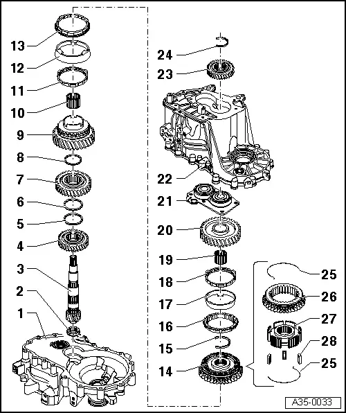
| 1 - | clutch housing |
| 2 - | Cylindrical roller bearing |
| q | With synchronizing ring |
| q | Remove → Fig. |
| q | Insertion → Fig. |
| q | Installation position: once the bearing is fitted, the ring should point towards the secondary shaft |
| 3 - | Secondary shaft |
| q | A matched pair with the wheel drive; they must be replaced together |
| q | Check the seating or the inner cylindrical bearing ring for damage or scoring |
| q | If the seating or the inner cylindrical bearing ring shows scoring or damage then replace the secondary shaft and the cylindrical roller bearing |
| 4 - | 4th speed selector gear |
| q | Installation position; the collar is orientated towards the 3rd gear → Fig. |
| 5 - | Circlip |
| 6 - | Circlip |
| 7 - | 3rd speed selector gear |
| q | Installation position; the collar is orientated towards the 3rd gear → Fig. |
| 8 - | Circlip |
| 9 - | 2nd gear wheel |
| 10 - | Needle roller bearing |
| q | For 2nd gear |
| 11 - | Inner ring of 2ndª gear |
| q | Check for wear → Fig. |
| q | Installation position → Fig. |
| 12 - | Outer ring of 2ndª gear |
| q | Fit to the inner ring → Item |
| q | Replace this if there are grooves or treads caused by wear |
| q | Installation position → Fig. |
| 13 - | Synchroniser ring for 2nd gear |
| q | Check for wear → Fig. |
| q | Installation position → Fig. |
| 14 - | Mobile element with synchromesh body of 1 and 2 gear |
| q | After fitting the securing ring → Item release the bearing allotment upwards → Fig. |
| q | Dismantling → Fig. |
| q | Assembling the mobile element/synchroniser body → Fig.and → Fig. |
| q | Installation position → Fig. |
| q | Insertion → Fig. |
| 15 - | Circlip |
| q | Releasing → Fig. |
| q | Insertion → Fig. |
| 16 - | 1st gear synchro-ring |
| q | Check for wear → Fig. |
| q | Fit so that the grooves insert in the locking elements of the mobile sleeve → Item |
| 17 - | Outer ring for 1st gear |
| q | Replace this if there are grooves or treads caused by wear |
| q | Fit on the synchroniser ring → Item fitting position → Fig. |
| 18 - | Inner ring for 1st gear |
| q | Check for wear → Fig. |
| q | Check that the tabs show no signs of wear |
| q | Installation position → Fig. |
| 19 - | Needle roller bearing |
| q | Of 1 gear |
| 20 - | 3rd speed selector gear |
| q | Installation position → Fig. |
| 21 - | Allotment with grooved ball bearings |
| q | Always replace the bearings with the allotment |
| q | Clean the allotment threaded holes (eg. with a 6 mm drill bit) |
| q | Releasing → Fig. |
| q | Insertion → Fig. |
| 22 - | Gearbox |
| 23 - | 5th speed selector gear |
| q | Installation position: the collar should be orientated towards the gearbox casing cover |
| 24 - | Circlip |
| q | Always replace. |
| q | Determine thickness |
| 25 - | Spring |
| q | Installation position → Fig. |
| 26 - | Mobile element |
| 27 - | Synchromesh hub |
| 28 - | Locking element |
| q | Quantity: 3 |