
Leon Mk1
| Differential: dismantling and assembly |

| Special tools and workshop equipment required |
| t | Gearbox extractor set -U-40100- |
| t | Gearbox repair set -U-40200- |
| t | Clip extractor with claws -T20022- |
| t | Electric blower -SAT 1416- |
| t | Digital thermometer -SAT 4002- |
 Note!
Note!| t | Heat the inner roller bearing track to 100 °C before fitting |
| t | The two roller bearings should be replaced together |
| t | Adjust the differential whenever the roller bearings are replaced → Chapter |

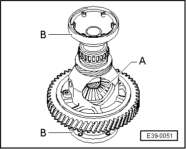
| 1 - | Gearbox casing |
| 2 - | Shim S1 |
| q | For differential |
| q | Always 1 mm thickness |
| 3 - | Outer track, roller bearing |
| q | Remove → Fig. |
| q | Fit → Fig. |
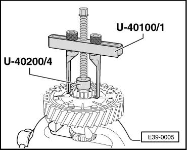
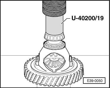
| 4 - | Roller bearing |
| q | Remove → Fig. |
| q | Fit → Fig. |
| 5 - | Differential crown |
| q | Removing and fitting → Chapter |
| q | Install: refer to section Code letters, group numbers, ratios, filling quantities → Chapter |
| 6 - | Set of thrust washers |
| q | Fit with gear oil |
| 7 - | Planet gear |
| q | Fit → Fig. |
| 8 - | Component to secure the aticulation flange |
| 9 - | Satellite |
| q | Fit → Fig. |
| 10 - | Satellite shaft |
| q | Remove with a drift |
| 11 - | Speedometer gear |
| q | Remove levering with a screwdriver |
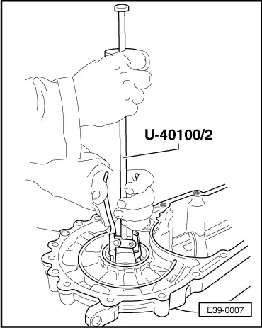
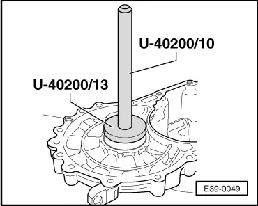
| 12 - | Roller bearing |
| q | Remove → Fig. |
| q | Fit → Fig. |
| 13 - | Outer track, roller bearing |
| q | Remove → Fig. |
| q | Fit → Fig. |
| 14 - | Shim S2 |
| q | For differential |
| q | etermine thickness → Chapter |
| 15 - | Clutch housing |
| 16 - | Bracket |
| q | Secure the satellite shaft in the gearbox with the rivetted crown wheel |
| q | It is secured with the rivets of the diffferential crown wheel → Item |
| 17 - | Elastic pin |
| q | Fit to the centre of the shaft |
| 18 - | Differential casing |
| q | If replaced, refer to Adjustment chart → Chapter |
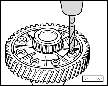
| 19 - | Rivet |
| q | Only for production |
| q | Drill → Fig. |
| q | Fit the crown wheel with bolts → Fig. |
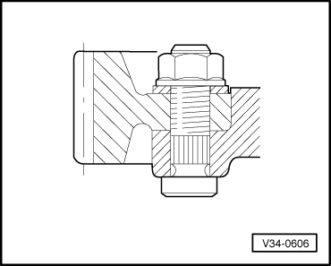
| 20 - | Nut |
| q | 70 Nm |
| 21 - | Differential crown wheel, rivetted or bolted |
| q | Rivetted on the production line |
| q | Bolt assembly → Fig. |
Note!
|
|
Note!
|
|
Note!
|
|
|
|
Note!
|
|
|
|