
Leon Mk1
|
|
|
 Note!
Note!
|
|
|
|
Note!
|
|
|
|
|
|
|
|
|
|
|
|
Note!
|
|
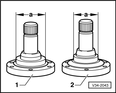
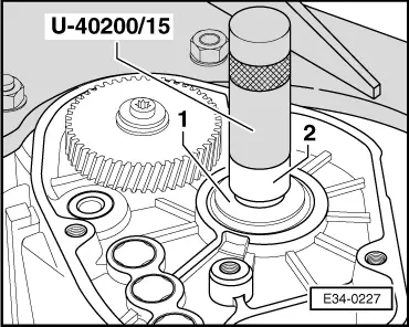
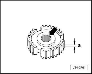
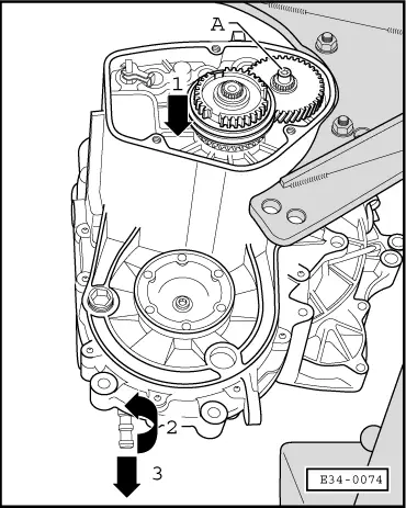
| Item | Flanged shaft | Dimension “a” |
| 1 | left-hand side of gearbox casing | 57 mm |
| 2 | right-hand side of gearbox casing | 48 mm |
|
|
|
|
|
|
|
|
|
|
Note!
|
|
|
|
|
|
|
|
Note!
|
|