
Leon Mk1
| Input shaft: adjusting |
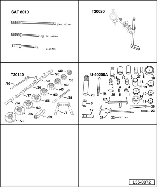
| Special tools and workshop equipment required |
| t | Torque spanners -SAT 8010- |
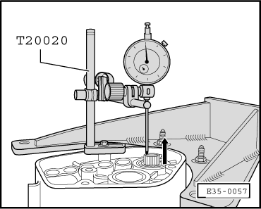
| t | Bracket -T20020- |
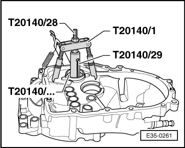
| t | Kit -T20140- |
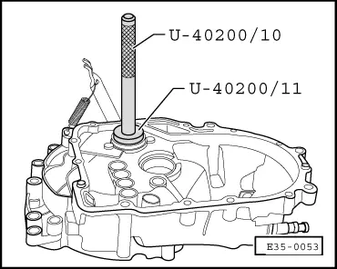
| t | Kit -U-40200A- |
|
 Note!
Note!
|
|
Note!
Note!
|
|
| Bearing play | Shim | |
| Average value (mm) | Thickness (mm) | N° of spares |
| 0.66 0.67 … 0.68 0.69 … 0.70 | 0.650 0.675 0.700 | 085 311 391 AN 085 311 391 N 085 311 391 AP |
| 0.71 … 0.73 0.74 … 0.75 0.76 … 0.78 | 0.725 0.750 0.775 | 085 311 391 P 085 311 391 AQ 085 311 391 Q |
| 0.79 … 0.80 0.81 … 0.82 0.83 … 0.85 | 0.800 0.825 0.850 | 085 311 391 AR 085 311 391 R 085 311 391 AS |
| 0.86 … 0.88 0.89 … 0.90 0.91 … 0.93 | 0.875 0.900 0.925 | 085 311 391 S 085 311 391 AT 085 311 391 T |
| 0.94 … 0.95 0.96 … 0.98 0.99 … 1.00 | 0.950 0.975 1.000 | 085 311 391 BA 085 311 391 AA 085 311 391 BB |
| 1.01 … 1.03 1.04 … 1.05 1.06 … 1.08 | 1.025 1.050 1.075 | 085 311 391 AB 085 311 391 BC 085 311 391 AC |
| 1.09 … 1.10 1.11 … 1.13 1.14 … 1.16 | 1.100 1.125 1.150 | 085 311 391 BD 085 311 391 AD 085 311 391 BE |
| Bearing play | Shim | |
| Average value (mm) | Thickness (mm) | N° of spares |
| 1.17 … 1.18 1.19 … 1.20 1.21 … 1.23 | 1.175 1.200 1.225 | 085 311 391 AE 085 311 391 BF 085 311 391 AF |
| 1.24 … 1.26 1.27 … 1.28 1.29 … 1.30 | 1.250 1.275 1.300 | 085 311 391 BG 085 311 391 AG 085 311 391 AN + AN |
| 1.31 … 1.33 1.34 … 1.36 1.37 … 1.38 | 1.325 1.350 1.375 | 085 311 391 AN + N 085 311 391 AN + AP 085 311 391 AN + P |
| 1.39 … 1.40 1.41 … 1.43 1.44 … 1.46 | 1.400 0.700 + 0.725 0.700 + 0.750 | 085 311 391 AP + AP 085 311 391 AP + P 085 311 391 AP + AQ |
| 1.47 … 1.48 1.49 … 1.50 1.51 … 1.53 | 0.700 + 0.775 0.700 + 0.800 0.700 + 0.825 | 085 311 391 AP + Q 085 311 391 AP + AR 085 311 391 AP + R |
| 1.54 … 1.56 1.57 … 1.58 1.59 … 1.61 | 0.700 + 0.850 0.700 + 0.875 0.700 + 0.900 | 085 311 391 AP + AS 085 311 391 AP + S 085 311 391 AP + AT |
| 1.62 … 1.63 1.64 … 1.66 1.67 … 1.68 1.69 … 1.70 | 0.700 + 0.925 0.700 + 0.950 0.700 + 0.975 0.700 + 1.000 | 085 311 391 AP + T 085 311 391 AP + BA 085 311 391 AP + AA 085 311 391 AP + BB |
|
|
|
|
|
Note!
|
|