
Leon Mk1
| Layshaft: dismantling and assembling |
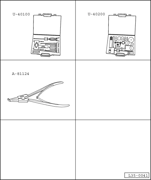
| Special tools and workshop equipment required |
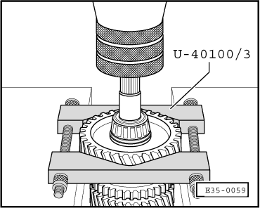
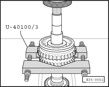
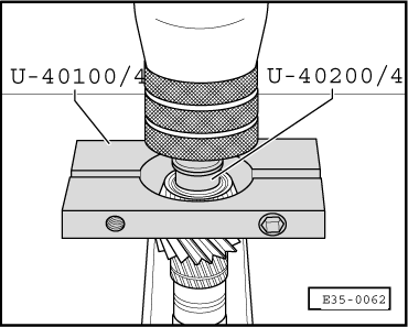
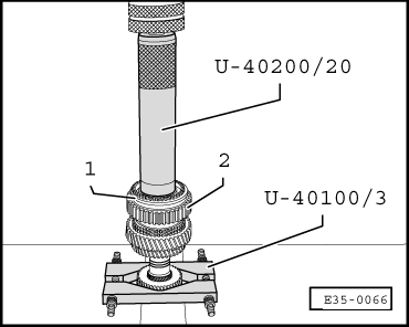
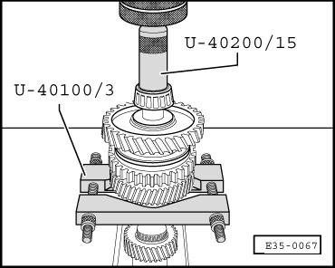
| t | Gearbox extractor set -U-40100- |
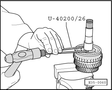
| t | Gearbox repair set -U-40200- |
| t | Circlip opening pliers -A-81124- |
 Note!
Note!| t | Whenever new gears or a new layshaft are fitted consult the technical data → Chapter, Code letters, group numbers, ratios, filling quantities |
| t | If the layshaft or the roller bearings are replaced, the layshaft must be adjusted → Chapter |
| t | The layshaft must be adjusted whenever elements have been replaced which could affect the position of the roller bearings. Refer to Adjustment chart → Chapter |
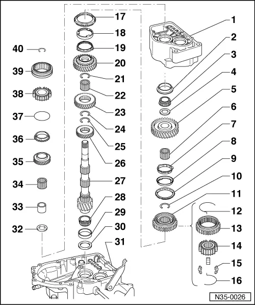
| 1 - | Gearbox casing |
| 2 - | Outer track, roller bearing |
| q | Remove → Fig. |
| q | Fit → Fig. |
| 3 - | Roller bearing |
| q | Remove together with 1st gear → Fig. |
| q | Fit → Fig. |
| 4 - | Stop washer |
| 5 - | Sliding 1st gear |
| q | Installation position → Fig. |
| 6 - | Needle roller bearing |
| q | For the sliding 1st gear |
| 7 - | Syncromesh ring |
| q | Inner ring for 1st gear |
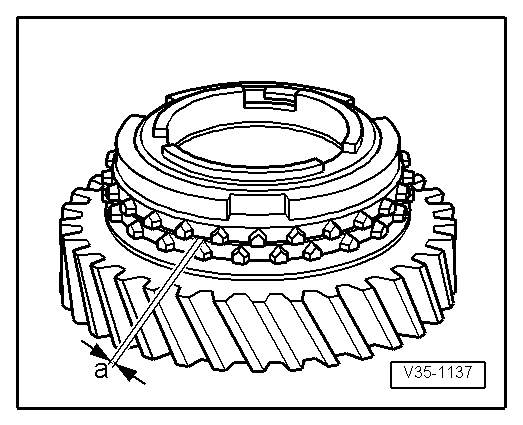
| q | Checking for wear → Fig. |
| q | Theck that the tabs show no signs of wear |
| q | Installation position → Fig. |
| 8 - | Outer ring for 1st gear |
| q | Fit it to the 1st gear syncromesh ring, item → Item |
| q | Installation position → Fig. |
| q | Replace if it shows signs of wear or grooves |
| 9 - | Syncromesh ring 1st gear |
| q | Checking for wear → Fig. |
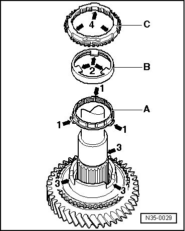
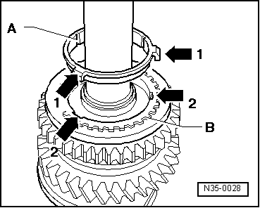
| q | On fitting, the tabs on the ring must fit into their housings in the syncromesh assembly for 1st and 2nd gear → Item |
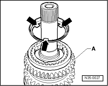
| 10 - | Circlip |
| q | Separation → Fig. |
| q | Location → Fig. |
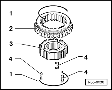
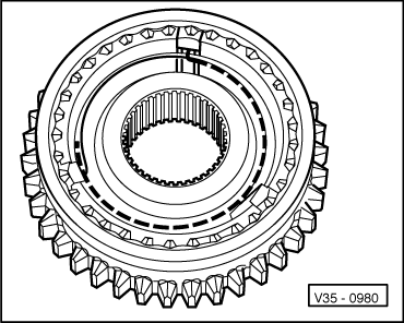
| 11 - | Syncromesh assembly for 1st and 2nd gear |
| q | They are matching pairs |
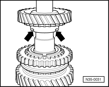
| q | Remove → Fig. |
| q | Assembly of components → Fig. und → Fig. |
| q | Fit → Fig. |
| 12 - | Spring |
| 13 - | Sliding sleeve |
| 14 - | Syncromesh hub |
| 15 - | Locking keyways |
| q | 3 units |
| 16 - | Spring |
| 17 - | Syncromesh ring 2nd gear |
| q | Checking for wear → Fig. |
| q | Installation position → Fig. |
| 18 - | Outer ring for 2nd gear |
| q | Fit to syncromesh ring → Item |
| q | Installation position → Fig. |
| q | Replace if it shows signs of wear or grooves |
| 19 - | Syncromesh ring |
| q | Inner ring for 2nd gear |
| q | Checking for wear → Fig. |
| q | Check that the tabs show no signs of wear |
| q | Installation position → Fig. |
| 20 - | Sliding 2nd gear |
| 21 - | Safety ring |
| q | Separation → Fig. |
| q | Location → Fig. |
| 22 - | Needle roller bearing |
| q | For sliding 2nd gear |
| 23 - | 3rd gear |
| 24 - | Circlip |
| q | Separation → Fig. |
| q | Location → Fig. |
| 25 - | Circlip |
| q | Separation → Fig. |
| q | Location → Fig. |
| 26 - | 4th gear |
| q | Assembly position: the identification groove should face the cone |
| 27 - | Layshaft |
| q | Check that the ratio (number of teeth) is correct → Chapter |
| q | Adjusting → Chapter |
| 28 - | Roller bearing |
| q | Remove → Fig. |
| q | Fit → Fig. |
| 29 - | Outer track, roller bearing |
| q | Remove → Fig. |
| q | Fit → Fig. |
| 30 - | Shim |
| q | For the layshaft |
| q | Determine thickness → Chapter |
| 31 - | Clutch housing |
| 32 - | Stop washer |
| q | The step of the shim should be facing the roller bearing |
| 33 - | Needle bearing bush |
| q | Remove → Anchor |
| q | Fit → Anchor |
| 34 - | Needle bearing for gear, 5th gear |
| 35 - | Sliding 5th gear |
| 36 - | Syncromesh ring 5th gear |
| 37 - | Spring |
| q | Fit onto the 5th gear syncromesh ring |
| q | Replace if it shows signs of wear |
| 38 - | Syncromesh hub 5th gear |
| q | Removal, fitting and adjustment → Chapter |
| 39 - | Sliding sleeve 5th gear |
| q | Removal, fitting and adjustment → Chapter |
| 40 - | Circlip |
Note!
|
|
Note!
|
|
|
|
|
|
 Warning
|
|
|
|
|
|
|
|
|
|
Note!
|
|
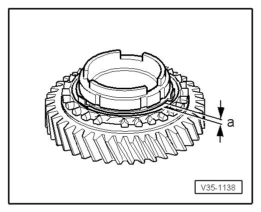
| Ring syncromesh | Measurement “a” on a new syncromesh | Wearlimit |
| 1st and 2nd gears | 0.75...1.25 mm | 0.3 mm |
|
|
| Ring syncromesh | Measurement “a” on a new syncromesh | Wearlimit |
| 1st and 2nd gears | 1.2...1.8 mm | 0.5 mm |
|
|
|
|
|
|
|
|
|
|
|
|
|
|
|
|