seat Workshop Repair Guides

SEAT Workshop Service and Repair Manuals

Final drive, differential, differential lock > < Layshaft: adjustment
Layshaft: adjusting
   
Layshaft: adjusting
Special tools and workshop equipment required
t  Torque spanners -SAT 8010-
t  Bracket -T20020-
t  Kit -T20140-
t  Kit -U-40200A-

Adjust the layshaft when one of the following elements have been replaced:
l  Gearbox casing
l  Clutch housing
l  Layshaft
l  Layshaft roller bearings
Refer to Adjustment chart → Chapter.
   
–  Fit the outer track of the layshaft roller bearings into the clutch housing, with a 0.75 mm thick shim.
–  Locate the layshaft in its housing in the gearbox casing.
  Note!
In gearboxes manufactured from 07.97, except those bearing the letters DQW, a 1 mm shim is fitted to the gearbox casing for the outer track of the roller bearing. Check that the shim is fitted.
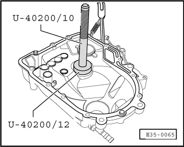
–  Fit the clutch housing onto the gearbox casing and tighten the securing bolts to 25 Nm.
  E35-0065
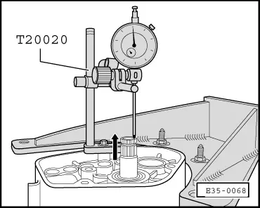
–  Fit tool -T20020- on the gearbox casing with a dial gauge. Locate the end of the dial gauge on the lay shaft.
–  Turn the layshaft to settle the roller bearings.
–  Adjust the dial gauge to “0” with a pre-tension of 1 mm.
  Note!
The adjustment to “0” of the dial gauge must be repeated every time the measurement is carried out. Otherwise the dial gauge will not return to the initial position.
–  Pull the layshaft in the direction of the dial gauge.
–  Take note of the measurement obtained (e.g. 0.30 mm).
  Note!
The dial gauge does not return to its initial position.
Shim calculation table
The bearing tension is obtained by adding a constant pressure value (0.2 mm) to the average value (0.3 mm) and the thickness of the shim fitted (0.75 mm).
  E35-0068
Washer fitted0.75 mm
+ Measured value0.30 mm
+ Pressure (const. value)0.20 mm
Shim thickness needed1.25 mm

The following shims are available:
   
Thickness (mm)Spare no.
0.70

0.75
0.80
0.85

0.90
0.95
1.00

1.05
1.10
1.15

1.20
1.25
1.30

1.35
1.40
020 311 391 Q

020 311 391
020 311 391 A
020 311 391 B

020 311 391 C
020 311 391 D
020 311 391 E

020 311 391 F
020 311 391 G
020 311 391 H

020 311 391 J
020 311 391 K
020 311 391 L

020 311 391 M
020 311 391 N

If the thickness needed is greater than those indicated on the table, two shims can be used.
–  Remove the bolts that secure both casings and separate the clutch housing.
–  Separate the layshaft.
   
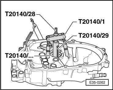
–  Remove the layshaft outer roller bearing track from the clutch housing, with tool -T20140-.
–  Procedure for extracting the outer track → Anchor.
–  Remove the 0.75 mm thick shim from the clutch housing.
  E35-0262
–  Fit the outer track of the roller bearing in the clutch housing with the correct shim (in this case 1.25 mm).
–  Lubricate the roller bearings with gearbox oil.
–  Locate the layshaft in its housing in the gearbox casing.
–  Fit the clutch housing onto the gearbox casing and tighten the bolts to 25 Nm.
  E35-0065

Final drive, differential, differential lock > < Layshaft: adjustment