
Leon Mk1
| Differential: dismounting and assembling |
| t | The differential must be adjusted whenever the tapered roller bearings are replaced. |
| t | The tapered roller bearings must always be removed together. Consult the Adjustments Chart → Chapter. |
| t | The tapered roller bearings and their corresponding external tracks are matched. Do not mix them up or exchange them with other bearings. |
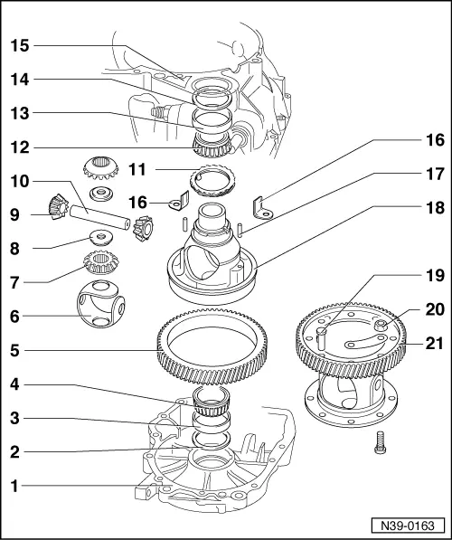
| 1 - | Gearbox casing |
| 2 - | Adjusting washer S1 for the differential |
| q | Always of 1 mm thickness |
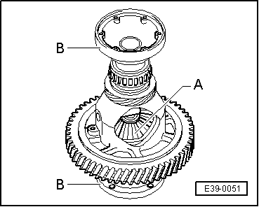
| 3 - | Outer track, tapered roller bearing |
| q | Dismounting → Fig. |
| q | Assembling → Fig. |
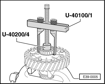
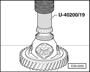
| 4 - | Tapered roller bearings |
| q | Dismounting → Fig. |
| q | Assembling → Fig. |
| 5 - | Riveted differential crown wheel |
| q | Dismounting and assembly → Chapter |
| q | Assembly: consult the Identification Initials section, group assignment, reduction ratios, filling capacities → Chapter |
| 6 - | Friction washer assembly |
| q | Impregnate with gear oil before assembling |
| 7 - | Sun gear |
| q | Assembly → Fig. |
| 8 - | Threaded cone for securing the coupled flanges |
| 9 - | Planetary gear |
| q | Assembly → Fig. |
| 10 - | Planetary gear shaft |
| q | Take out by tapping with a punch |
| 11 - | Speedometer mechanism pinion |
| q | Lever out with a flat screwdriver |
| 12 - | Tapered roller bearing |
| q | Dismounting → Fig. |
| q | Assembling → Fig. |
| 13 - | Outer track, tapered roller bearing |
| q | Dismounting → Fig. |
| q | Assembling → Fig. |
| 14 - | Adjusting washer S2 for the differential |
| q | Calculate the thickness → Chapter |
| 15 - | Clutch casing |
| 16 - | Bracket |
| q | Secure the planetary gear shaft in the gearbox with the riveted crown wheel |
| q | This is fixed with the rivets → Item of the crown wheel |
| 17 - | Spring pin |
| q | Insert to the centre of the shaft |
| 18 - | Differential housing |
| q | If replacing, consult the Adjustments chart → Chapter |
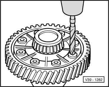
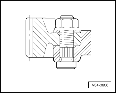
| 19 - | Rivet |
| q | Only for production |
| q | Drilling → Fig. |
| q | Assembly with screws → Fig. |
| 20 - | Nut, 70 Nm |
| 21 - | Riveted crown wheel |
| q | Riveted at the factory |
| q | Assembly with screws → Fig. |
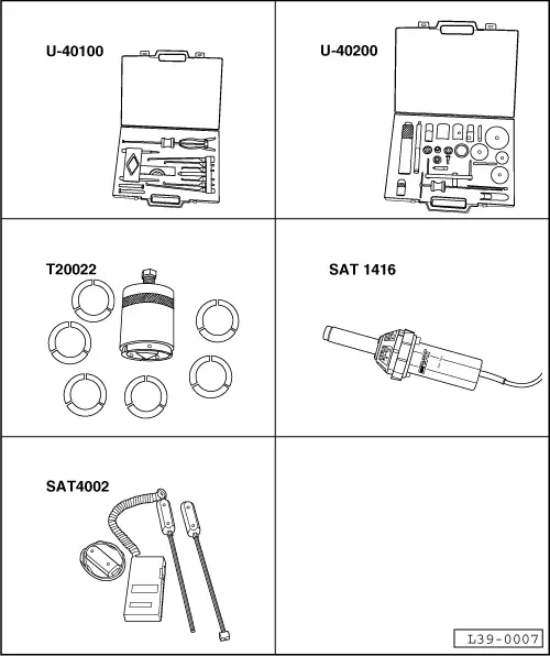
| Special tools and workshop equipment required |
| t | Case of extraction tools for gearboxes -U-40100- |
| t | Case of tools for repairing gearboxes -U-40200- |
| t | Pincer extractor tool with grippers -T20022- |
| t | Electrical blower -SAT 1416- |
| t | Digital thermometer -SAT 4002- |
 Note!
Note!
|
|
Note!
|
|
Note!
|
|
|
|
Note!
|
|
|
|