
Leon Mk1
| Clutch casing: repair |
| Assembly chart |
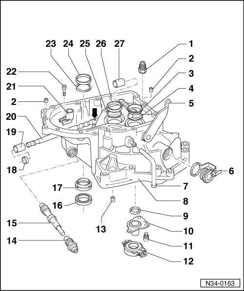
| 1 - | Grub screw for the selecting bar, 40 Nm |
| 2 - | Guide collar |
| q | 2 units |
| 3 - | Outer ring, tapered roller bearing |
| q | For primary shaft |
| q | Dismounting and assembly → Fig. |
| 4 - | Adjusting washer |
| q | For primary shaft |
| q | Calculate the thickness → Chapter |
| 5 - | Clutch release lever |
| q | Dismounting and assembly → Chapter |
| 6 - | Screw plug with closing cover |
| 7 - | Vent pipe |
| 8 - | Clutch casing |
| q | If being replaced, see adjustment chart → Chapter |
| q | Adjust the selector finger and drag link. |
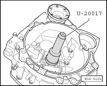
| 9 - | Primary shaft retainer |
| q | Dismounting → Fig. |
| q | Assembly → Fig. |
| 10 - | Guide collar |
| 11 - | Securing screw for the guide collar, 20 Nm |
| 12 - | Clutch release bearing |
| q | Dismounting and assembly → Chapter |
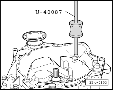
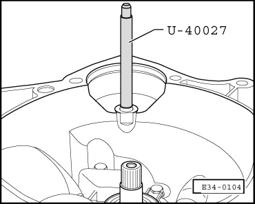
| 13 - | Bearing bush for the starter motor |
| q | Dismounting → Fig. |
| q | Assembly → Fig. |
| 14 - | Guide lug for speedometer mechanism shaft |
| 15 - | Speedometer mechanism shaft |
| 16 - | Right coupled flange retainer |
| q | Dismounting → Fig. |
| q | Assembly → Fig. |
| q | Replacement with the gearbox mounted in the vehicle → Chapter onwards |
| 17 - | Plate collar |
| q | For coupled flange retainer → Item |
| q | Dismounting → Fig. |
| q | Assembly → Fig. |
| 18 - | Gear selection lever oil seal |
| q | Remove carefully using a screwdriver as a lever → Fig. |
| q | Assembly → Fig. |
| q | Can be replaced with the gearbox mounted in the vehicle |
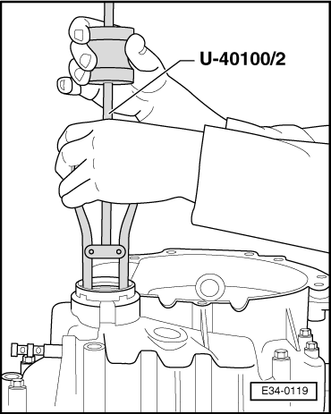
| 19 - | Front bearing bush for the selector shaft |
| q | Dismounting → Fig. |
| q | Assembly → Fig. |
| 20 - | Selector shaft |
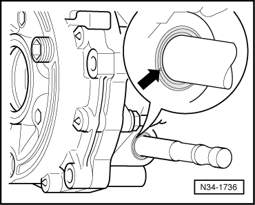
| q | Assembly position: the bevel edge -arrow- must face the guide collar → Item |
| q | Lubricate the sliding surfaces with molybdenum sulphide (MoS2)-based grease. |
| q | If replacing, adjust the selector finger and the guide collar → Chapter |
| 21 - | Guide collar |
| q | Adjustment → Chapter |
| 22 - | Securing screw for the guide collar, 25 Nm |
| 23 - | Adjusting washer for the differential |
| q | Calculate the thickness → Chapter |
| 24 - | Outer ring for the differential tapered roller bearing |
| q | Dismounting and assembly → Chapter |
| q | If replacing, adjust the differential → Chapter |
| 25 - | Adjusting washer for the secondary shaft |
| q | Calculate the thickness → Chapter |
| 26 - | Outer ring for the secondary shaft tapered roller bearing |
| q | Dismounting and assembly → Fig. |
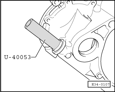
| 27 - | Rear bearing bush for the selector shaft |
| q | Dismounting → Fig. |
| q | Assembly → Fig. |
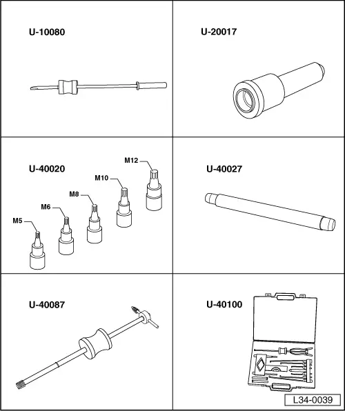
| Special tools and workshop equipment required |
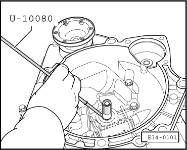
| t | Impact retainer extractor -U-10080- |
| t | Primary shaft retainer assembly tool -U-20017- |
| t | Notched socket set XZN -U-40020- |
| t | Tool for attaching the starter motor bush -U-40027- |
| t | Taps for Ø11 and Ø14 with percussor -U-40087- |
| t | Replacement parts extractor case -U-40100- |
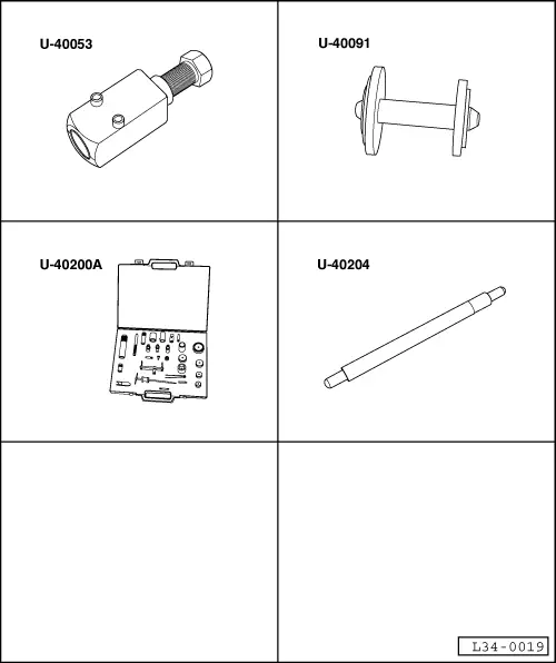
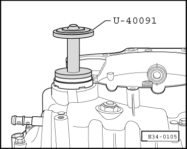
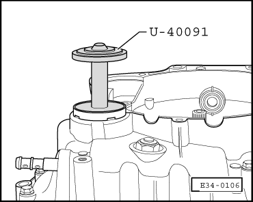
| t | Tool for attaching the drive train-differential retainer and bush -U-40091- |
| t | Tool for dismounting/assembling the selector shaft bush and retainer -U-40053- |
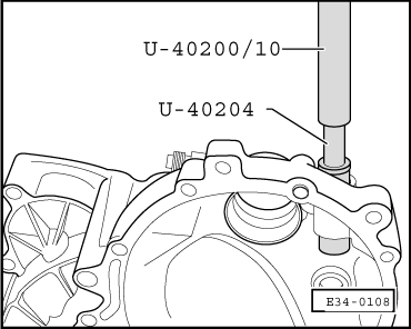
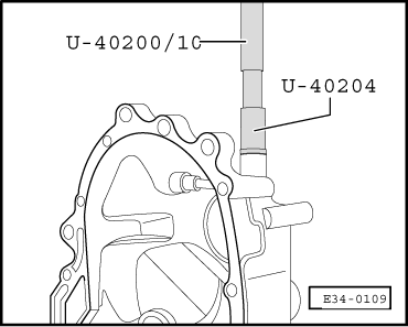
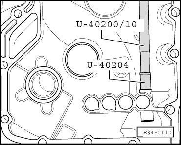
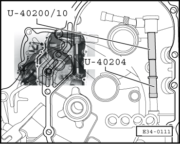
| t | Replacement parts case -U-40200- |
| t | Tool for dismounting/assembling the selector shaft bearing bush -U-40204- |
|
|
|
|
|
|
|
|
 Note!
Note!
|
|
|
|
Note!
|
|
|
|
|
|
|
|
|
|
|
|
|
|